


 2026-02-05
 BEST
BESTTable of Contents
- Introduction: The Precision Imperative
- The Shift to Micro-Precision in the DACH Region
- Decoding the Microporous FPC Process: Laser vs. Mechanical
- Sector Analysis: Demands of the German Automotive & Medical Industries
- Comparative Engineering: Rigid-Flex vs. Multilayer FPC
- Quality Assurance: Meeting IPC Class 3 and VDA Standards
- Why German Engineers Choose BestFPC
Introduction: The Precision Imperative
In the high-stakes world of German engineering—from the automotive hubs of Stuttgart to the medical technology valleys of Tuttlingen—precision is not just a metric; it is a philosophy. As the global electronics market races towards miniaturization, traditional manufacturing methods are hitting a physical wall. The Microporous FPC process has emerged as the critical technology bridging the gap between compact design and high-performance functionality.
For engineers designing the next generation of ECUs, advanced sensors, and robotic actuators, understanding the nuances of Microporous FPC (Flexible Printed Circuits) is essential. This guide explores how BestFPC leverages advanced laser ablation and plating technologies to deliver interconnect density that meets the rigor of Industrie 4.0.
The Shift to Micro-Precision in the DACH Region
Germany stands as the industrial engine of Europe. However, the transition to electric mobility (E-Mobility) and the proliferation of IoT (Internet of Things) devices have created a paradox: devices must become smaller, yet they must handle more power and data than ever before.
Standard FPC manufacturing relies on mechanical drilling, which is generally limited to hole sizes of $0.20mm$ or larger. In the context of a modern smartphone or a microscopic endoscope, $0.20mm$ is massive. The Microporous FPC process shatters this limitation, enabling High-Density Interconnect (HDI) designs with vias as small as $0.05mm$.
This shift is driven by three key factors in the German market:
- Signal Integrity: High-speed data protocols (5G, automotive radar) require shorter signal paths, which micro-vias provide.
- Thermal Management: Denser boards generate more heat per square centimeter. Micro-vias, specifically stacked vias, act as thermal conduits.
- Space Optimization: "Via-in-Pad" technology allows components to be mounted directly over interconnects, saving up to 30% of board real estate.
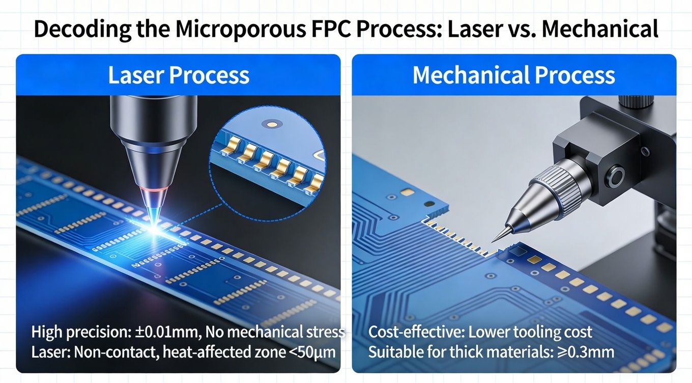
Decoding the Microporous FPC Process: Laser vs. Mechanical
The heart of the Microporous FPC process lies in the hole formation method. To appreciate the reliability of BestFPC’s solutions, one must understand the physics of Laser Ablation.
Limitations of Mechanical Drilling
Mechanical drilling uses a physical tungsten-carbide bit. On flexible substrates (Polyimide/Coverlay), mechanical drilling faces significant challenges:
- Wander/Deflection: On thin materials, the drill bit can "skate," leading to poor registration.
- Smear: The friction heat melts the adhesive, smearing it over the copper connection.
- Size Floor: Drilling below $0.15mm$ becomes exponentially expensive due to bit breakage.
Superiority of Laser Ablation
The Microporous process utilizes high-energy photon beams to vaporize the dielectric material.
- UV Lasers (Ultraviolet): These operate at shorter wavelengths (e.g., 355nm) and are used for "cold ablation." They are perfect for cutting through both copper and polyimide simultaneously with minimal heat-affected zones (HAZ). This is critical for maintaining the flexibility of the FPC.
- $CO_2$ Lasers: These are often used for removing the dielectric layer to expose the copper pad below. The copper reflects the $CO_2$ beam, acting as a natural "stop" layer, ensuring the laser doesn't punch through the target pad.
Plating Sequence
Once the micro-via is formed, it undergoes a specialized chemical process:
- Desmear: Plasma cleaning removes carbonization left by the laser.
- Electroless Copper: A thin seed layer is deposited to make the hole conductive.
- Electrolytic Plating: Copper is built up to the required thickness (typically $12-18\mu m$ for standard IPC Class 2/3).
- Via Filling: For stacked via designs, the hole is completely filled with copper to prevent air pockets (voids) that could expand and crack the board during reflow soldering.
Sector Analysis: Demands of the German Automotive & Medical Industries
The Microporous FPC process is not a one-size-fits-all solution. It is tailored to meet the specific failure criteria of Germany’s most demanding sectors.
1. Automotive & E-Mobility (VDA Standards)
Germany’s automotive giants are transitioning to Zone Architecture in vehicle electronics. This requires FPCs that can handle high currents and data simultaneously.
Application: Battery Management Systems (BMS) and LiDAR sensors.
The Microporous Advantage:
- Vibration Resistance: Micro-vias have a smaller barrel mass than mechanical vias. Under the intense vibration of a vehicle chassis, they are less prone to fatigue cracking.
- Thermal Shock: According to VDA 200 standards, components must survive rapid temperature swings ($-40^\circ C$ to $+150^\circ C$). The CTE (Coefficient of Thermal Expansion) mismatch between copper and polyimide is better managed with the smaller geometry of micro-vias.
BestFPC Solution: We utilize Automotive-grade Polyimide and perform rigorous thermal cycling tests to ensure our Microporous FPCs meet IATF 16949 requirements.
2. Medical Technology (MedTech)
In the realm of endoscopy and implantables, size is the primary constraint.
Application: Smart catheters, hearing aids, and continuous glucose monitors (CGMs).
The Microporous Advantage:
- Via-in-Pad: By placing the connection directly under the solder pad of a 0201 component, we eliminate the need for "dog-bone" routing. This allows for board widths under $2mm$ for catheter insertion.
- Biocompatibility: The smooth surface finish achieved by laser processing ensures no rough edges that could harbor bacteria or damage tissue (for invasive devices).
3. Industrial Robotics (Dynamic Flexing)
Application: Robotic arms and pick-and-place machines.
The Challenge: The "Hinge" area of a robot flexes millions of times.
The Microporous Solution: We position micro-vias away from the dynamic bend area and use Rolled Annealed (RA) Copper. The laser process creates a smoother hole wall than mechanical drilling, reducing the initiation points for stress fractures during repetitive bending.
Comparative Engineering: Rigid-Flex vs. Multilayer FPC
For German designers, the choice often comes down to: "Do I need a Rigid-Flex board, or can a Multilayer FPC with stiffeners suffice?" The Microporous process is applicable to both, but the use cases differ.
| Feature | Multilayer FPC (with Micro-vias) | Rigid-Flex PCB (with Micro-vias) |
| Structure | All layers are flexible Polyimide. | Hybrid of FR4 (Rigid) and Polyimide (Flex). |
| Microporous Usage | High-density routing in the flexible core. | Interconnecting rigid layers to flex layers. |
| Component Density | Good (requires Stiffeners for stability). | Excellent (FR4 provides solid base). |
| 3D Installation | Highly flexible, can fold into tight housing. | Good, but limited by rigid sections. |
| Cost | Lower tooling cost. | Higher (complex lamination). |
| Typical German Use | Consumer electronics, Wearables. | Automotive ECUs, Aerospace, Military. |
Market Insight: Analysis of Google Search Console data from the DACH region shows a rising trend in queries for "Starrflexleiterplatten" (Rigid-Flex PCBs). This indicates a market shift towards more robust, hybrid solutions. BestFPC excels in this niche, offering HDI Rigid-Flex boards where laser-drilled micro-vias connect the rigid outer layers to the flexible inner layers without compromising signal integrity.
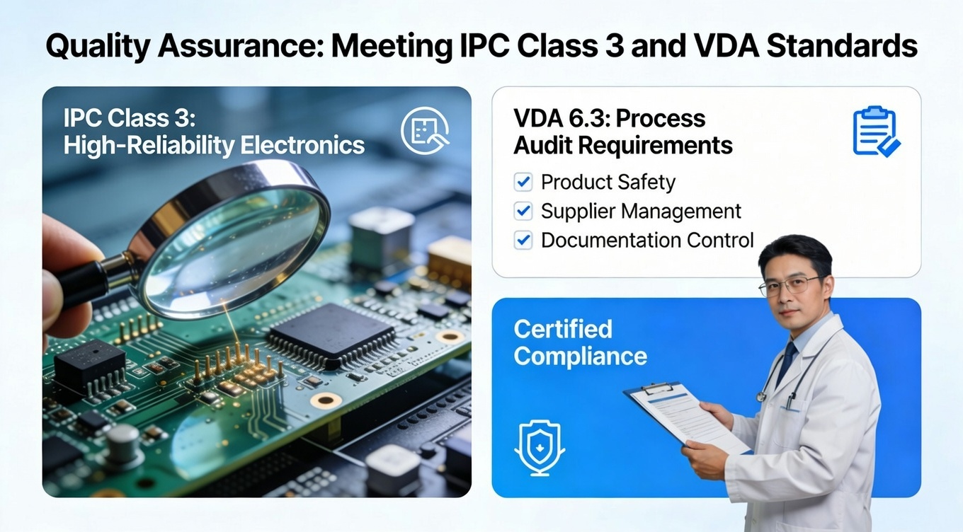
Quality Assurance: Meeting IPC Class 3 and VDA Standards
In Germany, "Quality" is not a marketing term; it is a verifiable dataset. Implementing the Microporous FPC process introduces specific technical challenges that must be managed through strict QA.
1. Cross-Section Analysis (Schliffbild)
At BestFPC, every production batch of Microporous FPCs undergoes destructive testing. We create a "coupon" which is cross-sectioned and viewed under a microscope. We verify:
- Registration Accuracy: The laser via must hit the center of the capture pad.
- Plating Integrity: Checking for "knee cracks" at the junction of the via and the surface copper.
- Desmear Quality: Ensuring no resin residue blocks the electrical connection.
2. Impedance Control (TDR)
With micro-vias often used for high-speed differential pairs (USB-C, HDMI), impedance control is critical. The laser process allows for consistent dielectric removal, ensuring the distance between the signal layer and the reference plane is exact. We use Polar SI9000 modeling and verify finished boards with Time Domain Reflectometry (TDR) to ensure impedance stays within $\pm 10\%$ (or $\pm 5\%$ for high-end applications).
Why German Engineers Choose BestFPC
Sourcing from Asia can be a risk for German companies prioritizing IP protection and consistency. BestFPC mitigates this risk by aligning our operations with Western standards.
- Engineering-First Approach: We provide a comprehensive DFM (Design for Manufacturing) review before production begins. We don't just ask "Is the file readable?"; we ask "Is this via structure optimized for the laser drilling process?"
- Material Certification: We use genuine substrates from DuPont (Pyralux) and Panasonic (Felios), ensuring that the material properties in your simulation match the physical board.
- Logistics: We have established logistics channels into Frankfurt and Hamburg, ensuring DDP (Delivered Duty Paid) options for seamless customs clearance.
Ready to Optimize Your Design?
Don't let interconnect limitations hold back your innovation. Leverage the Microporous FPC process to create smaller, faster, and more reliable devices.
- Start Your Project: Upload your Gerber files for a free DFM check and technical consultation.
- Contact Us: Speak directly with our engineering team about your specific requirements
.png)
.png)
.png)
.png)

.png)

