


 2026-02-05
 BEST
BESTTable of Contents
- 1. Understanding Minimum Line Width and Line Spacing for Flexible Board
- 2. German & International Design Standards for Flexible PCB Tolerances
- 3. Key German Industries and Their Line Width Requirement
- 4. How to Optimize Line Width and Spacing for Reliabilit
- 5. Choosing the Right Flex PCB Supplier for German Market
- 6. FAQ: Flex PCB Line Width, Spacing, and Design Rules
- 7. Conclusion & Next Steps for German Designers
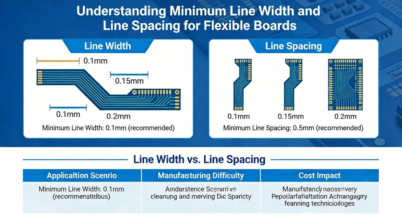
Understanding Minimum Line Width and Line Spacing for Flexible Boards
In flex PCB (flexible printed circuit) design, minimum line width and line spacing define the smallest copper traces and gap between them that can be reliably manufactured and still meet electrical, mechanical, and reliability requirements. For flex circuits, these parameters are more stringent than for rigid boards because the flexible substrate undergoes dynamic bending and must maintain electrical continuity under stress.
Typical industry minimums for flexible boards are:
- Minimum trace width: around 0.05 mm (50 µm)
- Minimum spacing: around 0.075 mm (75 µm) or higher in most advanced fabrication environments.
Manufacturers such as EuropePCB list minimum line width and spacing of 0.045–0.05 mm as part of their capability specifications, indicating that advanced flex fabrication can handle fine geometries required for dense interconnects.
Line Width vs. Line Spacing in Flex PCB Design
Line width refers to the width of the copper conductor trace, while line spacing refers to the minimum gap between adjacent traces. These two dimensions work together to determine key electrical and mechanical outcomes:
- Electrical Performance: Narrower lines and closer spacing can increase capacitance and crosstalk, potentially affecting signal integrity at high frequencies.
- Manufacturability: Tight tolerances require more precise tooling, laser imaging, and etching control.
- Reliability under Flexing: Too narrow or tightly spaced lines may crack under bending stress unless compensated with enhanced layout strategies like serpentine patterns or controlled bend radii.
German engineers often ask for wider spacing on dynamic flex areas to improve reliability, especially when boards are repeatedly bent or subjected to vibration.
Manufacturing Capabilities and Practical Limits
Fabrication houses differentiate performance by capability. For example, some flexible board producers list:
- Minimum line/space down to 3–4 mil (~0.076 mm) for rigid-flex designs.
- Standard flex board suppliers may support 0.05 mm line/space with controlled tolerances.
- Tolerances vary with copper weight and process controls — extremely thin lines (< 0.05 mm) require high-precision imaging and etch compensation protocols.
In the German electronics ecosystem — where high reliability is a must — engineers often define minimum line width and spacing in design specifications to match both functional and manufacturability expectations.
German & International Design Standards for Flexible PCB Tolerances
Flexible PCB design in Germany aligns with both international best practices and region-specific quality expectations. While there is no Germany-unique standard for minimum line width and spacing, most manufacturers and designers reference:
- IPC-2223: Design standard for flexible printed boards
- IPC-6013: Qualification and performance specification for flexible circuits
- ISO 9001: Quality management systems applied to PCB manufacturing
These standards provide robust guidance on feature sizes, tolerances, and test methods that ensure flexible board performance — especially where dynamic reliability and repeatable manufacturing are critical.
For example, IPC-2223 recommends conservative line widths based on copper thickness, etch factor, and required current carrying capacity, while IPC-6013 outlines processing performance metrics that tied line spacing directly to product class (Class 1 general, Class 2 commercial, Class 3 high reliability).
In German engineering culture, using documented standards in specification sheets not only improves product reliability but also simplifies supplier selection and audit processes.
Key German Industries and Their Line Width Requirements
Different application sectors in Germany have distinct design constraints that influence how flex PCB line width and spacing are specified:
Automotive & E-Mobility
In automotive electronics and E-Mobility — such as battery management systems, ADAS modules, and power converters — line width and spacing must support high current paths while maintaining signal reliability under thermal cycling and vibration. Wider traces with balanced spacing are often preferred for power interconnects, while fine pitch may be used for signal layers. Automotive OEMs often specify standards referencing IPC qualifications and OEM-specific protocols.
Industrial Automation & Machinery
German industrial systems — including robotics and factory automation — demand long lifespan and minimal downtime. Flex circuits used in moving joints or vibration-prone environments require careful spacing to avoid crack propagation. Typical minimums are often 0.075 mm or more in critical flex zones to ensure long-term mechanical resilience.
Medical Devices
In medical electronics — such as diagnostic systems, imaging modules, and wearable patient monitors — designers balance miniaturization demands with patient safety and reliability. Fine line widths (50–75 µm) with appropriate spacing are common, and manufacturers must document traceability and test results to support regulatory submissions.
Telecommunications & 5G Infrastructure
Germany’s 5G infrastructure uses flexible PCBs in small cell and edge computing modules where high-frequency signal integrity is critical. Smaller line and space requirements may be tolerated where controlled impedance and simulation-guided layout ensure signal performance.
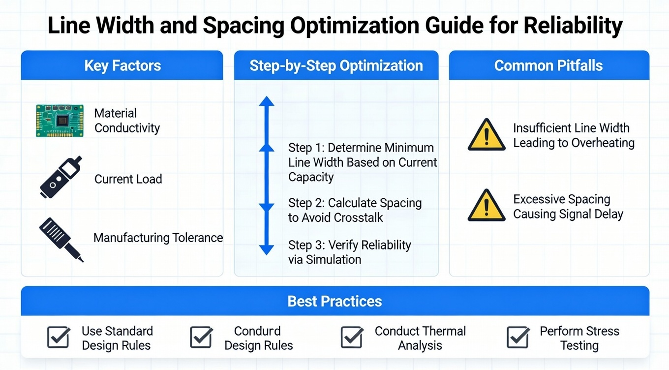
How to Optimize Line Width and Spacing for Reliability
Designing flex boards with appropriate line width and spacing is a balance between manufacturability, electrical requirements, and mechanical reliability.
Material Selection
Flexible substrates, typically polyimide with thin copper foils, influence the minimum feasible line and space. Thinner copper layers allow smaller traces but require careful etch compensation to prevent over-etching.
Bending and Flex Stress Considerations
Bend zones require special layout strategies such as gradual curvature, avoidance of 90° corners, and maintaining adequate spacing to reduce stress concentration. Overly thin lines in dynamic flex areas can crack prematurely.
Signal Integrity & Impedance Challenges
For signal layers, line width and spacing affect characteristic impedance. Germany’s high-performance electronics often specify controlled impedance PCB design, where precise line width and spacing are combined with electromagnetic simulation to achieve the target impedance performance.
Through design tools and simulation software, engineers can adjust trace geometries to meet both electrical and manufacturability goals.
Choosing the Right Flex PCB Supplier for German Market
Selecting a manufacturing partner involves evaluating process capability, quality systems, and documentation practices:
- Process capability: Ability to robustly produce minimum line widths and spacing with controlled tolerances.
- Quality systems: ISO 9001 and IPC standards aligned processes.
- Engineering support: Ability to refine DFM and anticipate flex reliability issues.
- Traceability: Detailed records of materials, copper weight, and process parameters.
A supplier that only manufactures to generic minimums may not support high-reliability German applications effectively.
FAQ: Flex PCB Line Width, Spacing, and Design Rules
Q1: What is a typical minimum line width for flexible boards?
Industry practice typically ranges from 0.05 mm (50 µm) and above depending on substrate and process. For many precision boards, 0.075 mm or 0.1 mm is chosen to balance manufacturability and reliability.
Q2: How does line spacing affect flex board reliability?
Closer spacing can increase risk of shorts under flex stress. German designers often increase spacing in dynamic flex zones to reduce stress concentration and improve lifecycle performance.
Q3: Can flexible boards handle fine line and space like rigid HDI?
Yes — with advanced fabrication techniques and process controls, flexible boards can achieve similar minimums, but designers must consider dynamic reliability and bending constraints.
Conclusion & Next Steps for German Designers
Minimum line width and line spacing are foundational to reliable flex PCB design, especially in demanding German application domains like automotive, industrial automation, medical, and telecommunications. Understanding industry practices, aligning with IPC and ISO standards, and working with a manufacturer capable of precision line/space control are essential steps.
For German engineers and procurement teams looking for high-precision flexible or rigid-flex PCB solutions matched to specific line width and spacing requirements, BESTFPC delivers advanced manufacturing capability, quality systems, and engineering support that meet stringent European and German expectations. Whether it’s multi-layer FPCs or soft-hard combination boards, BESTFPC can help bridge design to reliable production outcomes.
.png)
.png)
.png)
.png)

.png)

