


 2026-05-19
 BEST
BESTSoft PCB
Design & Manufacturing: Complete Switzerland Market Guide for Flexible Circuit Boards
Master soft PCB design principles, material selection, manufacturing processes, and supplier evaluation for Switzerland market. Learn flexible circuit design fundamentals, design considerations, material properties, manufacturing techniques, and how to choose reliable soft PCB suppliers. Essential guide for Swiss electronics engineers, product designers, and manufacturing companies seeking to develop innovative flexible circuit solutions.
Table of Contents
- Introduction: Soft PCB in Switzerland
- Soft PCB Fundamentals and Basics
- Soft PCB Design Principles and Best Practices
- Material Selection for Soft PCB Applications
- Critical Design Considerations for Soft PCBs
- Soft PCB Manufacturing Process Overview
- Switzerland Market Applications and Requirements
- Supplier Selection Criteria for Soft PCBs
- Common Questions About Soft PCB Design
- Why Choose BESTFPC for Soft PCB Solutions?
- Frequently Asked Questions (FAQ)
Introduction: Soft PCB in Switzerland
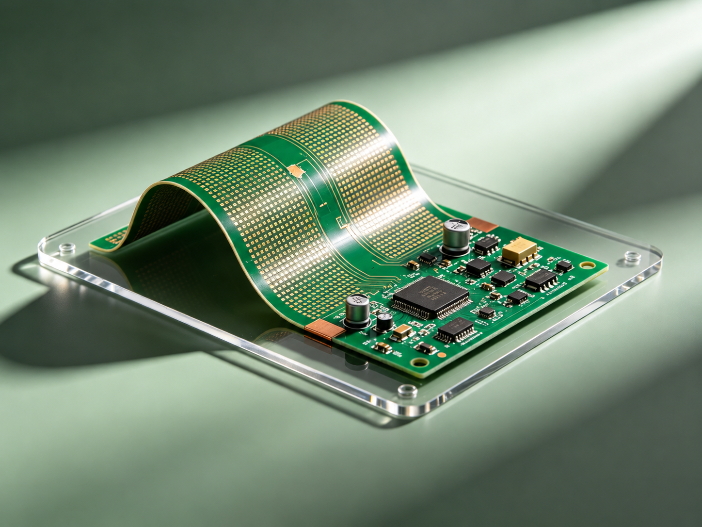
Soft PCB (also called flexible PCB or flex circuit) is a printed circuit board manufactured on flexible substrate materials like polyimide, allowing the circuit to bend, twist, and conform to three-dimensional shapes. Unlike rigid PCBs, soft PCBs provide unprecedented design flexibility, enabling innovative product designs in wearables, medical devices, automotive electronics, and consumer electronics. Switzerland's reputation for precision engineering, medical device innovation, and high-tech manufacturing makes soft PCB technology increasingly critical for Swiss electronics companies.
Switzerland's electronics industry is characterized by precision, innovation, and quality. Swiss companies lead in medical device manufacturing, pharmaceutical packaging, automotive electronics, industrial automation, and consumer electronics. The country's strong emphasis on quality, reliability, and innovation drives demand for advanced flexible circuit solutions. Swiss engineers and procurement teams seek soft PCB suppliers who understand precision requirements, quality standards, and the unique demands of Swiss manufacturing.
Understanding soft PCB design principles, material properties, and manufacturing processes is essential for Swiss product developers and procurement teams. This comprehensive guide explores soft PCB design fundamentals, material selection strategies, manufacturing techniques, and supplier evaluation criteria specifically tailored to Switzerland's electronics manufacturing landscape. Whether you're developing wearable medical devices, automotive electronics, consumer wearables, or industrial applications, mastering soft PCB design enables innovative product development and successful commercialization. BESTFPC brings 19 years of specialized flexible PCB design and manufacturing expertise, providing Swiss companies with precision soft PCB solutions that meet stringent quality standards.
Soft PCB Fundamentals and Basics
Soft PCB (flexible PCB) is fundamentally different from rigid PCB in materials, construction, and application possibilities. Understanding soft PCB basics helps Swiss engineers make informed design decisions and leverage soft PCB capabilities effectively.
What is Soft PCB?
Soft PCB is a printed circuit board manufactured on flexible substrate materials, typically polyimide (PI) or polyethylene terephthalate (PET). The flexible substrate allows the circuit board to bend, twist, fold, and conform to three-dimensional shapes without damage. Soft PCBs combine the electrical functionality of traditional PCBs with mechanical flexibility, enabling innovative product designs impossible with rigid PCBs.
Key Characteristics of Soft PCB
Flexibility
Can bend, twist, and fold repeatedly without damage. Enables conformal designs that fit complex 3D shapes. Polyimide typically supports 100,000+ bend cycles.
Thin Profile
Typically 0.1-0.3mm thickness, much thinner than rigid PCBs. Enables compact designs and space-constrained applications. Reduces overall product weight and volume.
Lightweight
Significantly lighter than rigid PCBs due to thin substrate and flexible materials. Critical for wearable and portable applications where weight matters.
Thermal Performance
Polyimide substrate provides excellent thermal stability (-60°C to +200°C). Maintains electrical properties across wide temperature ranges.
Chemical Resistance
Polyimide is highly resistant to chemicals, solvents, and environmental contaminants. Ideal for harsh operating environments.
Electrical Performance
Supports high-speed signal transmission, impedance control, and complex circuit designs. Suitable for analog, digital, and RF applications.
Soft PCB vs Rigid PCB comparison: Soft PCBs offer flexibility, thin profile, and lightweight design, but typically cost more and have longer lead times. Rigid PCBs are more economical for high-volume production but cannot bend or conform to shapes. Rigid-flex PCBs combine both technologies for applications requiring both rigid and flexible sections.
Soft PCB Design Principles and Best Practices
Effective soft PCB design requires understanding unique design principles and constraints. Swiss engineers must master soft PCB design fundamentals to create reliable, manufacturable flexible circuits.
Core Design Principles
1. Design for Flexibility: Avoid sharp bends and stress concentrations. Use gradual curves and generous bend radii (minimum 10x substrate thickness). Plan bend locations and stress relief areas during design phase. Distribute stress across circuit to prevent fatigue failures.
2. Layer Optimization: Minimize layer count to reduce thickness and cost. Single-layer designs are most economical and flexible. Dual-layer designs offer more routing options. Multi-layer designs reduce flexibility and increase cost. Use single-layer designs when possible, dual-layer when necessary.
3. Trace and Pad Design: Use wider traces (0.15-0.25mm minimum) to improve flexibility and reduce stress concentration. Larger pads (0.5-1.0mm) improve solderability and mechanical strength. Avoid sharp corners—use rounded traces. Maintain adequate spacing between traces to prevent short circuits during bending.
4. Via Placement: Position vias away from bend areas to prevent via cracking. Use larger vias (0.3-0.4mm) for better mechanical strength. Avoid via arrays in high-stress areas. Consider via-in-pad designs for high-density applications.
5. Stiffener Integration: Use stiffeners (polyimide, aluminum, or copper) in non-flex areas to provide mechanical support for components. Stiffeners prevent component damage during bending. Design stiffener edges to avoid stress concentration. Typical stiffener thickness: 0.5-1.0mm.
Design for Manufacturability (DFM) Best Practices
Minimum Feature Sizes: Trace width 0.15mm, trace spacing 0.15mm, via diameter 0.3mm. Smaller features increase cost and manufacturing complexity.
Aspect Ratio: Maintain aspect ratio (depth/diameter) ≤ 10:1 for vias. Higher ratios increase manufacturing difficulty and cost.
Pad Design: Use teardrop pads for vias to improve mechanical strength. Avoid isolated pads without trace connections.
Component Placement: Mount components on stiffener areas only. Avoid components on flex sections. Use surface-mount components (SMD) for better reliability.
Connector Design: Use flex-rated connectors designed for repeated flexing. Avoid standard rigid connectors on flex sections. Provide strain relief at connector interfaces.
Material Selection for Soft PCB Applications
Material selection is critical for soft PCB performance, reliability, and cost. Swiss engineers must understand material properties and select appropriate materials for specific applications.
| Material | Properties | Temperature Range | Typical Applications | Cost |
|---|---|---|---|---|
| Polyimide (PI) | Excellent thermal stability, chemical resistance, flexibility. Industry standard. | -60°C to +200°C | Medical devices, automotive, industrial, consumer electronics | Mid-range |
| PET (Polyester) | Good flexibility, lower cost, lower temperature rating. Suitable for consumer applications. | -40°C to +80°C | Consumer wearables, low-cost applications | Low |
| LCP (Liquid Crystal Polymer) | High-speed signal transmission, excellent thermal performance. Premium material. | -40°C to +240°C | High-frequency RF applications, aerospace | High |
| Aramid (Kapton®) | Extreme thermal stability, excellent mechanical properties. Premium cost. | -60°C to +260°C | Aerospace, military, extreme environment applications | Very High |
| PEEK (Polyetheretherketone) | Superior mechanical and thermal properties. Biocompatible for medical applications. | -60°C to +250°C | Medical implants, aerospace, high-reliability applications | Very High |
Material Selection Criteria for Swiss Applications
Medical Device Applications: Polyimide or PEEK materials. Biocompatibility certification required. Chemical resistance for sterilization processes. Polyimide is standard for most medical devices; PEEK for implantable applications.
Automotive Electronics: Polyimide with wide temperature range (-40°C to +125°C). Excellent thermal stability and chemical resistance. Meets AEC-Q200 standards. Reliability for automotive environment.
Consumer Wearables: PET or polyimide depending on performance requirements. PET is more economical for cost-sensitive applications. Polyimide for higher reliability and longer lifespan.
Industrial Applications: Polyimide for harsh environments. Chemical resistance for industrial solvents and contaminants. Thermal stability for high-temperature operations.
Critical Design Considerations for Soft PCBs
Successful soft PCB design requires careful consideration of multiple factors beyond basic circuit design. Swiss engineers must address these critical considerations to ensure reliable, manufacturable soft PCBs.
Bend Radius and Flex Cycles
Minimum bend radius depends on substrate thickness and material. Typical minimum: 10x substrate thickness. For 0.1mm substrate: minimum 1mm bend radius. Flex cycle life depends on bend radius and material. Polyimide typically supports 100,000+ cycles at minimum bend radius. Design for expected flex cycles in application.
Component Selection and Placement
Use flex-rated components designed for repeated flexing. Avoid standard rigid components on flex sections. Mount components on stiffener areas only. Use surface-mount devices (SMD) for better reliability. Avoid through-hole components on flex sections. Consider component weight and stress on flex substrate.
Connector and Interface Design
Use flex-rated connectors designed for repeated mating cycles. Provide strain relief at connector interfaces to prevent stress concentration. Avoid standard rigid connectors on flex sections. Consider connector durability for application requirements. Test connector reliability for expected flex cycles.
Thermal Management
Polyimide substrate has lower thermal conductivity than copper or aluminum. Use thermal vias and copper pours for heat dissipation. Consider thermal stiffeners for high-power components. Monitor temperature rise during operation. Ensure thermal design meets application requirements.
Signal Integrity and EMI
Maintain impedance control for high-speed signals. Use ground planes for EMI shielding. Minimize trace length for critical signals. Avoid routing sensitive signals near high-current traces. Consider shielding for RF applications. Test signal integrity for high-speed designs.
Environmental Protection
Consider conformal coating for moisture protection. Use solder mask for corrosion resistance. Evaluate encapsulation for harsh environments. Plan for environmental testing (salt spray, humidity, thermal cycling). Ensure design meets environmental requirements for application.
Soft PCB Manufacturing Process Overview
Understanding soft PCB manufacturing helps Swiss engineers design for manufacturability and appreciate manufacturing complexity. Soft PCB manufacturing involves specialized processes different from rigid PCB production.
Manufacturing challenges: Soft PCB manufacturing is more complex than rigid PCB. Flexible substrate requires careful handling to prevent damage. Precision is critical to maintain electrical properties. Lead times typically longer than rigid PCB (2-8 weeks). Cost higher due to specialized processes and materials.
Switzerland Market Applications and Requirements
Switzerland's electronics industry drives demand for advanced soft PCB solutions. Swiss companies lead in medical devices, pharmaceuticals, automotive electronics, and precision manufacturing. Understanding Switzerland-specific applications and requirements helps engineers design appropriate soft PCB solutions.
Medical Device Applications
Switzerland is a global leader in medical device manufacturing. Soft PCBs enable innovative wearable medical devices, diagnostic equipment, and implantable devices. Medical applications require biocompatibility certification, sterilization compatibility, and strict quality standards. Polyimide and PEEK materials are standard for medical applications. ISO 13485 certification required for medical device suppliers.
Pharmaceutical Packaging Electronics
Swiss pharmaceutical companies increasingly use electronics in packaging and monitoring. Soft PCBs enable smart packaging with temperature monitoring, authentication, and tracking. Chemical resistance critical for pharmaceutical environment. Sterilization compatibility required. Flexible designs enable integration into packaging structures.
Automotive Electronics
Swiss automotive suppliers use soft PCBs for advanced vehicle electronics. Applications include sensor integration, control modules, and lighting systems. Wide temperature range (-40°C to +125°C) required. AEC-Q200 reliability standards required. Vibration resistance critical for automotive environment.
Industrial Automation
Swiss industrial equipment manufacturers use soft PCBs for compact, flexible sensor and control systems. Applications include robotic systems, precision instruments, and automated machinery. Reliability and durability critical. Environmental protection required for factory environments.
Consumer Electronics and Wearables
Swiss consumer electronics companies develop innovative wearable devices using soft PCB technology. Applications include fitness trackers, health monitoring devices, and smart textiles. Cost-effectiveness important for consumer market. Durability for daily wear required. Aesthetic design considerations.
Switzerland Quality and Regulatory Requirements
ISO 9001: Quality management system certification required. Ensures consistent quality and process control.
ISO 13485: Medical device quality management. Required for medical device suppliers.
IATF 16949: Automotive quality standards. Required for automotive suppliers.
RoHS Compliance: Restriction of Hazardous Substances. EU regulation compliance required.
CE Marking: Conformity assessment for European market. Required for many electronics products.
Supplier Selection Criteria for Soft PCBs
Choosing the right soft PCB supplier is critical for project success. Swiss procurement teams must evaluate suppliers carefully based on multiple criteria beyond just price.
| Selection Criteria | Why It Matters | How to Evaluate | Red Flags |
|---|---|---|---|
| Design Expertise | Supplier should offer design consultation and DFM analysis to optimize designs for manufacturability and cost. | Request design review samples, ask about design optimization experience, verify DFM capabilities. | Supplier unwilling to discuss design or offer optimization suggestions. |
| Quality Certifications | ISO 9001, ISO 13485 (medical), IATF 16949 (automotive) ensure consistent quality and compliance. | Verify certifications, request audit reports, confirm certification scope. | Missing required certifications or expired certifications. |
| Manufacturing Capability | Supplier should have equipment and expertise for required specifications (layer count, trace width, materials). | Verify equipment capabilities, request capability matrix, discuss process control. | Supplier uncertain about capabilities or limited equipment. |
| Material Selection | Supplier should offer appropriate materials (polyimide, PET, LCP) for application requirements. | Verify material options, request material certifications, confirm material sourcing. | Limited material options or inability to source specialty materials. |
| Lead Times | Affects project timeline and supply chain planning. Shorter lead times enable faster product development. | Request lead times for prototypes and production volumes, verify consistency. | Unrealistic lead times or inability to meet commitments. |
| Quality Control | Rigorous testing and inspection ensure product reliability and compliance with specifications. | Request quality control procedures, verify testing capabilities, review test reports. | Inadequate testing or quality control procedures. |
| Communication & Support | Responsive communication and technical support ensure smooth project execution and problem resolution. | Assess responsiveness to inquiries, verify technical support availability, check communication channels. | Slow response times or poor communication. |
Supplier evaluation strategy: Request samples from 2-3 suppliers. Compare quality, lead times, and pricing. Request design consultation and DFM analysis. Verify certifications and quality control procedures. Establish long-term relationships with reliable suppliers for consistent quality and better pricing.
Common Questions About Soft PCB Design
Below are answers to common questions Swiss electronics engineers ask about soft PCB design and manufacturing.
What is the difference between soft PCB and rigid PCB?
Soft PCB uses flexible substrate (polyimide, PET) allowing bending and flexing. Rigid PCB uses rigid substrate (FR-4, ceramic) that cannot bend. Soft PCBs are thinner, lighter, and enable 3D designs. Rigid PCBs are more economical for high-volume production. Rigid-flex PCBs combine both technologies.
What is the minimum bend radius for soft PCB?
Minimum bend radius typically 10x substrate thickness. For 0.1mm substrate: minimum 1mm radius. For 0.2mm substrate: minimum 2mm radius. Smaller bend radii increase stress and reduce flex cycle life. Design should accommodate minimum bend radius requirements.
How many times can soft PCB be bent?
Flex cycle life depends on bend radius, material, and design. Polyimide typically supports 100,000+ cycles at minimum bend radius. Larger bend radii support more cycles. Design should account for expected flex cycles in application. Stress concentration points reduce cycle life.
What materials are available for soft PCB?
Common materials: Polyimide (PI) - industry standard, excellent thermal stability; PET - economical, lower temperature rating; LCP - high-speed applications, premium cost; PEEK - biocompatible, medical applications; Aramid - extreme environments. Material selection depends on application requirements and budget.
What is the typical lead time for soft PCB?
Prototypes: 2-4 weeks. Low-volume production (100-500): 3-6 weeks. High-volume production (1,000+): 4-8 weeks. Lead times vary by complexity, material availability, and supplier capacity. Plan ahead for soft PCB projects due to longer lead times vs. rigid PCB.
Can soft PCB support high-speed signals?
Yes, soft PCB can support high-speed signals with proper design. Use impedance-controlled traces, ground planes for shielding, and minimize trace length. Material selection affects high-speed performance. LCP material better for RF applications. Polyimide suitable for most digital applications.
What is the cost difference between soft PCB and rigid PCB?
Soft PCB typically costs 2-5x more than rigid PCB due to specialized materials and processes. Cost depends on complexity, volume, and material selection. Polyimide is mid-range cost. PET is more economical. Specialty materials (LCP, PEEK) are premium cost. Volume discounts available for large orders.
How do I design soft PCB for manufacturability?
Follow DFM guidelines: use wider traces (0.15mm minimum), larger pads (0.5mm minimum), avoid sharp corners, position vias away from bend areas, use stiffeners for components, minimize layer count. Consult supplier during design phase for optimization suggestions. Request DFM analysis before manufacturing.
Why Choose BESTFPC for Soft PCB Solutions?
BESTFPC brings 19 years of specialized flexible PCB design and manufacturing expertise. We provide Swiss companies with precision soft PCB solutions that meet stringent quality standards and support innovative product development.
BESTFPC's commitment to soft PCB excellence is demonstrated through design expertise, quality certifications, fast turnaround, and proven track record serving Swiss electronics companies. We provide not just soft PCBs, but partnership for your innovation success.
Frequently Asked Questions (FAQ) About Soft PCB Design
Below are answers to the most frequently asked questions about soft PCB design, materials, and manufacturing.
Get Your Soft PCB Solution Today
BESTFPC provides expert soft PCB design and manufacturing for Swiss electronics companies. 19 years of experience, ISO certifications, and commitment to quality.
.png)
.png)
.png)
.png)

.png)

