


 2026-06-12
 BEST
BESTFlex PCB Stackup
Complete Design Guide for Optimal Flexible Circuit Performance
Quick Navigation
- Introduction: Flex PCB Stackup Fundamentals
- Flex PCB Stackup Basics and Terminology
- Layer Configuration and Design
- Material Selection for Stackup
- Impedance Control and Signal Integrity
- Thermal Management in Stackup Design
- Design Rules and Best Practices
- Common Stackup Configurations
- Frequently Asked Questions
- Why Choose BESTFPC?
Introduction: Flex PCB Stackup Fundamentals
Flex PCB stackup design is a critical aspect of flexible circuit board engineering that directly impacts electrical performance, mechanical reliability, and manufacturing feasibility. A well-designed stackup ensures optimal signal integrity, thermal management, and mechanical flexibility while maintaining cost-effectiveness. This comprehensive guide explores the principles, practices, and strategies for designing optimal flex PCB stackups.
The stackup defines the arrangement of conductive and dielectric layers in a flexible circuit board. Unlike rigid PCBs, flex PCB stackups must consider additional factors such as flexibility requirements, bend radius limitations, and the unique properties of flexible base materials. Understanding these considerations is essential for engineers and procurement professionals who need to specify or manufacture high-performance flexible circuits.
Flex PCB Stackup Basics and Terminology
Understanding flex PCB stackup terminology is essential for effective communication with manufacturers and design teams. The stackup is typically described from top to bottom, starting with the top copper layer and ending with the bottom copper layer, with all dielectric and adhesive layers specified in between.
Key Stackup Components
A typical flex PCB stackup consists of several key components: copper foil layers that carry electrical signals and power, dielectric base materials (typically polyimide) that provide electrical insulation, adhesive layers that bond copper to dielectric materials, and cover films that protect the circuit from environmental damage and provide additional insulation.
The thickness of each layer is precisely controlled to achieve desired electrical properties, mechanical characteristics, and manufacturing feasibility. Standard copper foil thicknesses include 12μm (1oz), 18μm (1.5oz), and 35μm (2oz), while dielectric materials are typically 25μm, 50μm, 75μm, or 125μm thick.
Stackup Notation and Specification
Flex PCB stackups are typically specified using a standardized notation that describes each layer from top to bottom. For example, a simple two-layer stackup might be specified as: Cover Film / Copper (12μm) / Adhesive / Polyimide (50μm) / Adhesive / Copper (12μm) / Cover Film. This notation provides clear communication of the stackup structure to manufacturing partners.
Layer Configuration and Design
Layer configuration in flex PCB stackup design involves strategic decisions about the number of layers, their arrangement, and their specific functions. These decisions directly impact electrical performance, mechanical flexibility, and manufacturing complexity.
Single-Layer Flex PCBs
Single-layer flex PCBs consist of a single copper layer laminated to a polyimide base material with cover film protection. These stackups are the simplest and most cost-effective, making them ideal for applications with straightforward electrical requirements and minimal space constraints. Single-layer stackups are commonly used in consumer electronics, simple sensors, and basic interconnect applications.
The typical single-layer stackup includes: Cover Film / Copper (12μm) / Adhesive / Polyimide (50μm) / Adhesive / Cover Film. This configuration provides adequate electrical insulation, mechanical protection, and manufacturing simplicity for many applications.
Two-Layer Flex PCBs
Two-layer flex PCBs provide increased design flexibility compared to single-layer designs, allowing for more complex circuit layouts, improved signal routing, and better ground plane implementation. Two-layer stackups are the most commonly used configuration in the industry, balancing performance, cost, and manufacturing complexity.
A typical two-layer stackup includes: Cover Film / Copper (12μm) / Adhesive / Polyimide (50μm) / Adhesive / Copper (12μm) / Adhesive / Polyimide (50μm) / Adhesive / Cover Film. This configuration allows for signal and ground planes, improving signal integrity and EMI performance.
Multi-Layer Flex PCBs
Multi-layer flex PCBs with three or more copper layers enable advanced designs with dedicated power planes, multiple signal layers, and improved thermal management. These stackups are used in high-performance applications such as aerospace systems, medical devices, and advanced automotive electronics.
Multi-layer stackups require careful design to ensure adequate flexibility in flex regions while maintaining structural integrity in rigid sections. Via placement, layer transitions, and material selection become increasingly critical in multi-layer designs.
Material Selection for Stackup
Material selection is fundamental to flex PCB stackup design, directly impacting electrical properties, mechanical characteristics, thermal performance, and manufacturing feasibility. Common materials include polyimide (PI), polyester (PET), and specialty materials like PEEK.
| Material | Temperature Range | Dielectric Constant | Flexibility | Cost | Typical Applications |
|---|---|---|---|---|---|
| Polyimide (PI) | -60°C to +200°C | 3.5 | Excellent | Moderate | Aerospace, Medical, Automotive |
| Polyester (PET) | -40°C to +120°C | 3.2 | Very Good | Low | Consumer Electronics, Wearables |
| PEEK | -60°C to +250°C | 3.2 | Good | High | Extreme Environment Applications |
| Aramid (Kapton) | -60°C to +220°C | 3.6 | Good | High | Aerospace, High-Reliability Applications |
Copper Foil Selection
Copper foil thickness and surface characteristics significantly impact electrical performance and mechanical reliability. Standard copper weights (12μm, 18μm, 35μm) are selected based on current-carrying requirements, impedance control needs, and mechanical strength requirements in flex regions.
Copper surface characteristics, including roughness and adhesion properties, affect signal integrity and manufacturing yield. High-profile copper foil improves adhesion but increases surface roughness, potentially affecting high-frequency performance. Low-profile copper foil provides better high-frequency characteristics but may have adhesion challenges.
Impedance Control and Signal Integrity
Impedance control is critical for high-speed flex PCB applications. Stackup design directly determines impedance characteristics through layer spacing, material dielectric constants, and trace geometry. Proper impedance control ensures signal integrity, minimizes crosstalk, and reduces EMI.
Impedance Calculation and Control
Impedance in flex PCBs is controlled through careful stackup design and trace geometry. The impedance of a microstrip trace depends on trace width, height above ground plane, dielectric constant of the material, and copper thickness. Stackup design determines the height above ground plane and material properties, while trace width is controlled during layout.
For controlled impedance applications, stackup design typically includes dedicated ground planes with specific spacing to signal layers. Common impedance targets include 50Ω for RF applications, 75Ω for video signals, and 85Ω/100Ω differential pairs for high-speed digital signals.
Signal Integrity Considerations
Beyond impedance control, stackup design affects signal integrity through layer spacing, material selection, and ground plane distribution. Adequate ground plane coverage, proper via stitching, and controlled layer spacing minimize crosstalk and reflections, ensuring reliable signal transmission at high speeds.
Thermal Management in Stackup Design
Thermal management becomes increasingly important in high-power flex PCB applications. Stackup design can significantly impact thermal performance through material selection, layer arrangement, and thermal via placement strategies.
Thermal Conductivity and Heat Dissipation
Different materials have varying thermal conductivity characteristics. Polyimide provides moderate thermal conductivity, while specialized materials like aluminum-filled polyimide or ceramic-filled materials offer enhanced thermal performance. Stackup design can incorporate thermal vias and copper planes to create heat dissipation paths from high-power components to external heat sinks.
Proper thermal stackup design reduces operating temperatures, extends component lifespan, improves reliability, and enables higher power density designs. Thermal analysis during stackup design phase helps identify potential hot spots and optimize thermal performance.
Design Rules and Best Practices
Following established design rules and best practices ensures flex PCB stackups are manufacturable, reliable, and cost-effective. These rules address minimum trace widths, spacing requirements, via sizing, and flex region considerations.
Flex Region Design Rules
Flex regions require special design considerations to ensure reliability during repeated bending. Minimum trace width in flex regions is typically 0.15mm, with minimum spacing of 0.15mm between traces. Vias should be avoided in flex regions or minimized to critical connections only, as vias create stress concentration points.
Traces in flex regions should be routed perpendicular to the bend direction when possible, and traces should be spaced at least 2mm from bend lines to prevent stress concentration. These design rules ensure flex regions can withstand hundreds of thousands of bend cycles without fatigue failure.
Rigid Region Design Rules
Rigid regions can accommodate higher density designs with tighter trace widths and spacing. Standard design rules for rigid regions include minimum trace width of 0.1mm, minimum spacing of 0.1mm, and standard via sizes of 0.3mm. These dimensions are achievable with standard manufacturing processes and provide good cost-effectiveness.
Common Stackup Configurations
Several stackup configurations are commonly used in industry applications. Understanding these standard configurations helps engineers make informed decisions about stackup design for their specific applications.
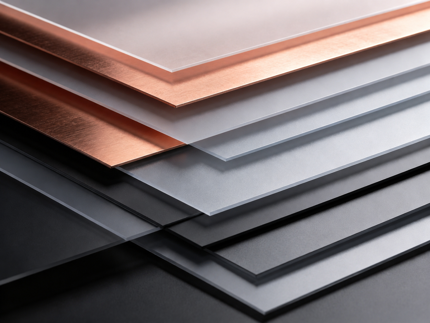
Standard Two-Layer Stackup
Typical Two-Layer Flex PCB Stackup
High-Speed Impedance-Controlled Stackup
For high-speed applications requiring impedance control, stackups typically include dedicated ground planes with precise spacing to signal layers. A typical high-speed stackup might include signal layers with 50Ω impedance, ground planes for return paths, and power planes for distribution.
Thermal Management Stackup
For high-power applications requiring thermal management, stackups incorporate thermal vias and copper planes optimized for heat dissipation. These stackups may include thicker copper layers (35μm) and specialized adhesive systems with enhanced thermal conductivity.
Frequently Asked Questions
What is the difference between flex PCB stackup and rigid PCB stackup?
Flex PCB stackups must consider flexibility requirements, minimum bend radius, and flex region design rules. Rigid PCB stackups focus on electrical performance and manufacturing efficiency without flexibility constraints. Flex stackups typically use polyimide base materials and specialized adhesive systems, while rigid PCBs use FR-4 or other rigid materials.
How do I determine the optimal number of layers for my flex PCB stackup?
The optimal number of layers depends on circuit complexity, signal integrity requirements, power distribution needs, and thermal management requirements. Start with the minimum number of layers required for functionality, then add layers as needed for ground planes, power planes, and signal routing. Two-layer stackups are most common, with multi-layer designs used for complex applications.
What is the minimum bend radius for flex PCBs?
Minimum bend radius depends on material thickness, copper weight, and design. Typical minimum bend radii range from 5mm to 25mm. Polyimide-based boards generally support tighter bend radii than polyester-based boards. The stackup design, particularly layer thickness and copper weight, directly impacts achievable bend radius.
How does stackup design affect impedance control?
Stackup design determines impedance through layer spacing, dielectric constant of materials, and trace geometry. Controlled impedance requires dedicated ground planes with specific spacing to signal layers. The dielectric constant of polyimide (typically 3.5) and layer spacing determine the impedance of traces. Proper stackup design enables 50Ω, 75Ω, or 85/100Ω differential impedance control.
What materials are best for thermal management in flex PCB stackups?
Polyimide provides moderate thermal conductivity, while specialized materials like aluminum-filled polyimide or ceramic-filled materials offer enhanced thermal performance. Stackup design can incorporate thermal vias and copper planes to create heat dissipation paths. For extreme thermal requirements, consider PEEK or other high-performance materials.
How many flex cycles can a flex PCB withstand?
Well-designed flex PCBs can withstand 100,000 to 1,000,000 flex cycles depending on material selection, stackup design, bend radius, and operating conditions. Polyimide-based boards typically support more cycles than polyester-based boards. Proper stackup design with adequate layer thickness and material selection maximizes flex cycle capability.
What is the typical cost impact of different stackup configurations?
Single-layer stackups are most cost-effective, with two-layer stackups adding approximately 30-50% to material costs. Multi-layer stackups add 50-100% or more depending on layer count and complexity. Material selection also impacts cost, with polyester being most economical and PEEK being most expensive. The cost-benefit analysis should consider performance requirements and volume.
How do I specify stackup tolerances and ensure manufacturing consistency?
Stackup specifications should include layer thickness tolerances, dielectric constant ranges, and copper weight specifications. Standard tolerances for layer thickness are typically ±10% or ±0.05mm. Working with experienced manufacturers who have established processes and quality control procedures ensures consistent stackup production.
Can stackup design affect manufacturing yield?
Yes, stackup design significantly affects manufacturing yield. Designs that follow established design rules, avoid extreme tolerances, and consider manufacturing capabilities typically achieve higher yields. Stackups that are too aggressive in layer thickness, spacing, or material selection may result in manufacturing defects and reduced yield.
How do I optimize stackup for high-frequency applications?
High-frequency stackup optimization includes controlled impedance design, minimized trace losses through material selection, and proper ground plane distribution. Use materials with low dielectric loss, maintain consistent layer spacing, and incorporate adequate ground planes. Simulation tools help verify high-frequency performance before manufacturing.
Why Choose BESTFPC for Flex PCB Stackup Design and Manufacturing?
BESTFPC is a leading manufacturer of flexible PCBs with 19 years of experience in stackup design and manufacturing. Our expertise spans simple single-layer designs to complex multi-layer stackups for demanding aerospace, medical, and automotive applications.
Our Stackup Design Expertise
Our engineering team has extensive experience designing stackups optimized for specific application requirements. We work closely with customers to understand their electrical, mechanical, and thermal requirements, then design stackups that balance performance, cost, and manufacturability.
We maintain a comprehensive database of proven stackup configurations for common applications, enabling rapid design iterations and faster time-to-market. Our design tools and simulation capabilities ensure stackups meet electrical performance targets before manufacturing begins.
Manufacturing Excellence and Quality
BESTFPC maintains ISO 9001, ISO 13485, and IATF 16949 certifications, demonstrating our commitment to quality and continuous improvement. Our manufacturing processes are optimized for stackup consistency, with tight process controls ensuring layer thickness, material properties, and electrical characteristics meet specifications.
Design Optimization
Expert stackup design for optimal electrical and mechanical performance
Quality Assurance
ISO 9001, ISO 13485, IATF 16949 certified manufacturing processes
Simulation Tools
Advanced simulation for impedance, thermal, and signal integrity verification
Fast Turnaround
Rapid prototyping and production capabilities for time-sensitive projects
Cost Optimization
Stackup designs optimized for cost-effectiveness without compromising performance
Global Support
Responsive technical support and customer service worldwide
Ready to Optimize Your Flex PCB Stackup?
Contact BESTFPC today to discuss your stackup requirements and discover how our expertise can help optimize your flexible circuit design.
Get Your Stackup Design Consultation Explore More Articles.png)
.png)
.png)
.png)

.png)

