HDI boards are a type of printed circuit board (PCB) technology that enables higher circuit density and smaller form factors compared to traditional PCBs. HDI boards are commonly used in applications where space is limited, such as mobile devices, wearables, and aerospace systems.
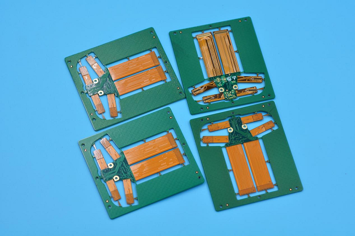
Ebest Circuit (Best Technology) has rich experience in HDI rigid flex pcb manufacturing, below is one of our 7 layers HDI rigid flex pcb.

In Ebest Circuit (Best Technology), our HDI board usually has the blind holes or buried holes, and the minimum hole size usually is 0.1mm. This board has the blind and buried holes, and the minimum hole size is 0.1mm. 100 ohm differential impedance control with 50 single ended impedance control. It's surface finish is ENIG, 1oz copper for outer layers, 1/2oz copper for inner layers, green solder mask with white silkscreen. total thickness is 1.4mm.
Here are some key features and aspects of HDI boards:
- High Density: HDI boards are designed to accommodate a large number of densely packed components and interconnections. They typically have multiple layers with high routing density, allowing for more complex circuitry in a smaller footprint.
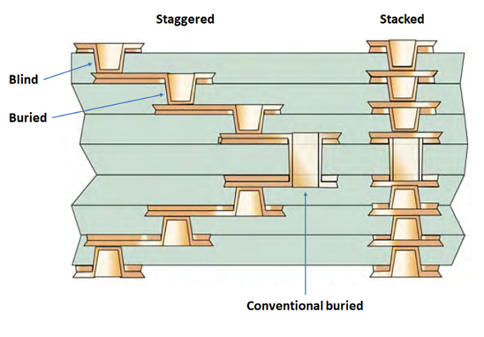
- Microvias: HDI boards extensively use microvias, which are very small holes drilled into the board to create electrical connections between different layers. Microvias are smaller in size compared to traditional vias, allowing for increased routing density.
- Staggered and Stacked Microvias: HDI boards employ different types of microvias, including staggered and stacked microvias. Staggered microvias connect adjacent layers, while stacked microvias connect non-adjacent layers, providing even higher routing density.

Blind and Buried Vias: HDI boards often utilize blind and buried vias, which are vias that do not extend through the entire board. Blind vias connect an outer layer with one or more inner layers, while buried vias connect inner layers only. These vias help optimize space and increase routing capabilities. - ine Pitch Components: HDI boards support the use of fine pitch components, such as microcontrollers, ball grid array (BGA) packages, and small surface-mount devices (SMDs). The high routing density and smaller features of HDI boards make them suitable for accommodating these tiny components.
- Increased Signal Integrity: HDI boards can provide improved signal integrity due to shorter trace lengths and reduced noise interference. The compact design minimizes signal loss and impedance mismatches, allowing for better performance in high-frequency applications.
- Design Considerations: Designing HDI boards requires expertise in factors such as layer stacking, via types, trace widths, and clearances. Advanced design software and manufacturing techniques are often employed to ensure precise alignment and reliability of the intricate interconnections.
- Manufacturing Challenges: HDI boards can be more challenging to manufacture compared to standard PCBs. The use of smaller features and complex layer structures requires specialized fabrication techniques, such as laser drilling, sequential lamination, and precise registration control.
HDI technology has become increasingly prevalent in the electronics industry, enabling the development of smaller, lighter, and more sophisticated devices. It offers enhanced electrical performance, improved reliability, and greater design flexibility. If you have any comments about the HDI board, please feel free to contact Ebest Circuit (Best Technology) Team e-mail: sales@bestfpc.com


 2023-07-04
 BEST
BEST

.png)
.png)
.png)
.png)

.png)

