


 2025-08-06
 BEST
BEST
Manufacturers of rigid and flexible pcb face persistent challenges in detecting defects, maintaining process consistency, and managing materials. These issues threaten reliability and increase costs, as failures in solder joint integrity or component inspection accuracy often lead to costly rework. With the rise of advanced inspection tools and statistical process control, companies strive to reduce defects in pcbs and rigid-flex pcbs. Industry leaders recognise that robust quality control directly improves reliability and aligns with stringent industry standards.
Key Takeaways
- Precise alignment and copper thickness control are vital to prevent defects like delamination and trace cracking in rigid and flexible PCBs.
- Effective moisture management and thermal design improve PCB reliability by reducing risks of delamination and overheating.
- Automated inspection systems, such as machine vision and AOI, enhance defect detection accuracy and speed, supporting consistent quality.
- Skilled personnel and thorough defect data analysis enable faster problem-solving and continuous quality improvements.
- Collaboration between design and manufacturing teams, combined with adaptable quality control processes, ensures reliable and customised PCB production.
Quality Control Challenges
Precision and Alignment
Manufacturers of rigid and flexible PCB encounter significant quality control challenges in achieving precise alignment during fabrication. The alignment of copper planes, especially at the rigid-flex interface, demands accuracy within ±50μm. Optical alignment systems play a vital role in maintaining this registration. In flexible PCB manufacturing, drilling and etching in flex regions require careful control. Low-feed drilling and laser drilling for microvias help prevent cracks and extend bend life.
Common failure modes include delamination at the rigid-flex interface, often caused by mismatched thermal expansion or improper lamination. Trace cracking in dynamic flex areas arises when design rules are violated or when the wrong copper type is used. These issues occur frequently enough to require multi-point verification, such as X-ray inspection, Automated Optical Inspection (AOI), and bend testing over 100,000 cycles.
Note: Misalignment can lead to shifted circuits, trace breakouts, delamination, and signal integrity problems. Strict process controls, precise CAD preparation, and specialised fabrication techniques are essential to maintain quality and reliability.
Manufacturers use rolled-annealed copper, adhere to bend radius guidelines, and implement multi-stage lamination to reduce failures. These rigorous quality control measures ensure that both rigid and flexible PCB products meet industry standards for reliability and performance.
Copper Thickness
Copper thickness presents another set of quality control challenges in both rigid and flexible PCB production. In flexible PCBs, the thickness and structure of copper—whether solid or mesh—directly affect heat dissipation, electromagnetic shielding, and mechanical reliability. Mesh copper reduces mass and improves heat management but lowers current capacity. The grid spacing in mesh copper must balance shielding effectiveness with manufacturability; improper spacing increases defects or reduces shielding.
Solid copper layers provide higher current capacity and mechanical strength but may reduce flexibility. For example, increasing copper from 1 oz to 2 oz nearly doubles current capacity and lowers hotspot temperatures by 15–20°C. Thicker copper also enhances vibration resistance, which is critical in automotive and aerospace applications. However, thicker copper increases manufacturing complexity and cost, requiring wider trace widths and spacing.
Manufacturers use hybrid copper stacks to optimise cost and performance, placing thicker copper on power layers and thinner copper on signal layers. Quality control includes maintaining copper thickness within ±10% for standard layers and ±20% for heavy copper. X-Ray Fluorescence (XRF) testing provides real-time, non-destructive measurement of copper thickness, ensuring consistency across production. Automated chemical dosing and inline monitoring further support rigorous quality control.
Moisture Sensitivity
Moisture sensitivity remains a persistent issue in PCB manufacturing processes. Both rigid and flexible PCBs can absorb moisture from the environment, which compromises adhesion between layers and leads to delamination or blistering during soldering. Flexible PCB manufacturing faces greater risk due to the use of polyimide and other hygroscopic materials.
Manufacturers address these challenges by storing materials in controlled environments and pre-baking laminates to remove absorbed moisture. They also use moisture-resistant adhesives and encapsulants to improve adhesion and reliability. Regular humidity monitoring and process audits form part of the quality control measures that reduce the risk of moisture-related defects.
Tip: Consistent control of environmental conditions and careful selection of materials help maintain high quality and reliability in both rigid and flexible PCB production.
Quality control challenges such as precision and alignment, copper thickness, and moisture sensitivity require ongoing attention. Manufacturers who implement rigorous quality control and adapt their processes to address these issues achieve higher reliability and product quality in the competitive PCB industry.
Manufacturing Challenges
Thermal Management
Thermal management stands as a critical challenge in PCB manufacturing. High component density often leads to concentrated heat generation in small areas. Standard materials such as FR4 offer low thermal conductivity, which limits heat dissipation and increases the risk of overheating. Cost constraints force manufacturers to balance advanced thermal materials with budget limitations. Harsh environments, including industrial and automotive settings, further complicate these challenges by exposing PCBs to high ambient temperatures.
Manufacturers face several consequences when thermal management fails:
- Overheating causes component failures and thermal runaway, raising defect rates during mass production.
- Poor heat dissipation results in reliability problems and higher warranty claims.
- Inconsistent thermal features across batches lead to uneven defect distribution.
To address these issues, manufacturers employ a range of techniques:
- They optimise component placement to spread heat and avoid hotspots, which can reduce temperatures by 10–15°C.
- Thermal vias transfer heat efficiently between layers, lowering component temperatures by up to 20°C.
- High-thermal-conductivity materials, such as metal-core PCBs, provide improved heat dissipation for power-intensive applications.
- Heat sinks and thermal interface materials further enhance heat removal, reducing component temperatures by 15–25°C.
- Cooling methods, including forced air and liquid cooling, are selected based on power levels and cost.
Early thermal simulation helps identify hotspots and optimise design before production, reducing costly redesigns and improving product quality.
Manufacturers also select materials and design strategies to improve thermal performance:
- Polyimide suits high-temperature, chemically resistant applications, especially in automotive and aerospace sectors.
- Ceramic substrates, such as aluminium nitride, offer exceptional thermal conductivity and low expansion, ideal for high-power devices.
- Metal-core PCBs, using aluminium or copper, provide excellent heat dissipation for LED lighting and power modules.
- High-Tg FR4 materials balance cost and thermal performance for automotive and military uses.
- Design strategies include thermal vias, copper pours, strategic component placement, and thermal paste application.
A table summarising common materials and their thermal properties:
| Material | Thermal Conductivity (W/m·K) | Typical Application |
|---|---|---|
| FR4 | ~0.3 | Consumer electronics |
| High-Tg FR4 | ~0.3 | Automotive, military |
| Metal-core (Al/Cu) | ~10 | LED, power modules |
| Ceramic (AlN) | >150 | High-power, military, radar |
| Polyimide | ~0.12 | Aerospace, automotive flex circuits |
Early evaluation of thermal requirements and collaboration with manufacturers ensure the right material and design choices, directly impacting product performance and reliability.
Lamination and Layering
Lamination and layering present persistent challenges in PCB manufacturing processes. Misalignment, resin starvation, and delamination frequently occur if process controls lack precision. Stepwise lamination prevents misalignment and resin starvation, while compatible adhesives such as Pyralux® GPL epoxy ensure strong layer bonding and reliable adhesion. Manufacturers must manage chemical compatibility among materials to avoid delamination, which can compromise both mechanical strength and electrical performance.
Dimensional control and precise Automated Optical Inspection (AOI) tuning help maintain layer alignment and quality. Early collaboration between design and fabrication teams prevents inappropriate lamination cycles or material mismatches. Lamination presses with precise control of temperature (up to 200°C) and pressure (up to 500 psi) avoid material distortion. Manufacturers apply heat and pressure to bond rigid and flexible layers using adhesives or prepreg layers.
Precision alignment, with tolerances within 0.05 mm, uses fixtures during lamination and drilling. Reinforcement of transition zones between rigid and flex sections with coverlay or stiffeners reduces stress and improves durability. Uniform heating and compatible adhesives prevent delamination caused by differing thermal expansion rates.
Consistent process controls and early design collaboration significantly reduce lamination-related defects and improve overall product quality.
Assembly Issues
Assembly issues remain a major concern in both rigid and flexible PCB manufacturing. Frequent problems include design errors, such as incorrect trace widths or spacing, which cause signal integrity problems or shorts. Material issues, like low-quality substrates or inconsistent copper thickness, lead to delamination and poor conductivity. Manufacturing mishaps, such as misalignment during component placement or insufficient soldering, result in open circuits or weak joints. Environmental factors, including dust, humidity, or temperature fluctuations, contribute to corrosion and soldering defects.
These issues impact final product quality in several ways:
- Signal integrity problems and shorts reduce device performance.
- Delamination and poor conductivity compromise reliability.
- Open circuits and weak joints increase failure rates.
- Corrosion leads to long-term degradation.
- Financial losses arise from scrap, rework, and delayed production schedules.
- Damaged reputation and loss of customer trust follow repeated failures.
Manufacturers implement robust quality control measures to mitigate these challenges. Automated Optical Inspection (AOI) detects surface-level defects rapidly and accurately. X-ray inspection identifies hidden internal defects, such as voids in solder joints and misaligned vias.
Best practices to reduce assembly-related defects include:
- Placing at least three panel fiducials in a triangular pattern near panel edges for accurate triangulation and rotation correction.
- Using fiducials with a diameter of about 1.5 mm and maintaining a clearance zone of at least 2 mm for visibility by machine vision systems.
- Keeping fiducials as bare copper without solder mask or silkscreen to ensure high contrast.
- Clearly documenting fiducial locations in design files and assembly notes.
- For multi-board panels, positioning fiducials on the panel frame rather than on breakaway tabs.
Panel fiducials serve as reliable reference points for automated assembly machines, reducing errors such as component misplacement and orientation mistakes. Their strategic use improves alignment accuracy, saves production time, and lowers costs by minimising SMT errors.
Manufacturers who adopt these practices achieve higher assembly quality, improved performance, and greater customer satisfaction. Addressing assembly issues at every stage of production ensures that PCBs meet stringent industry standards and deliver reliable performance in demanding applications.
Inspection and Testing
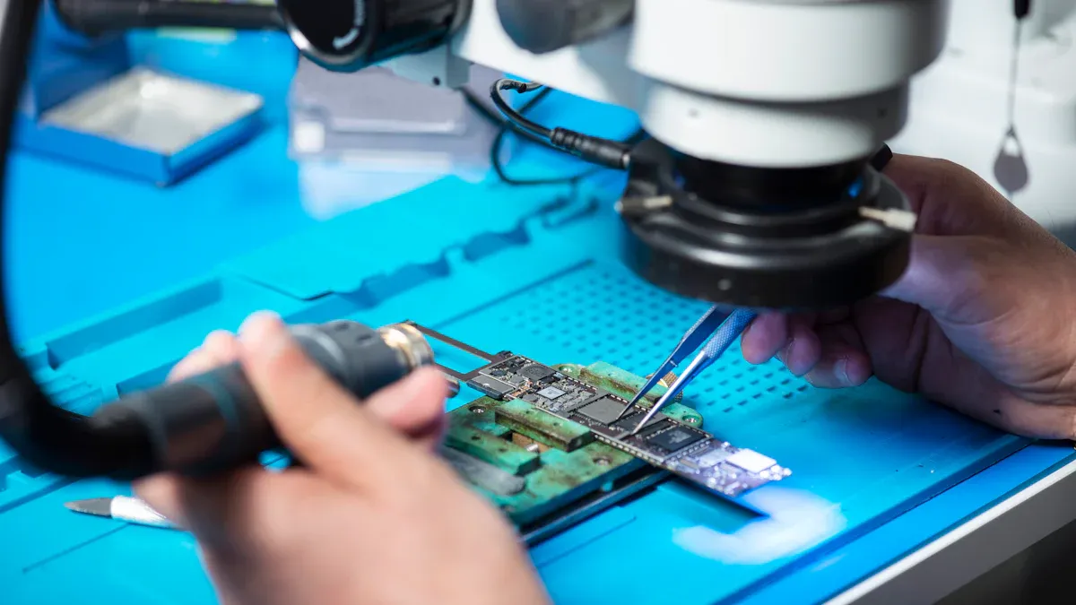
Machine Vision Systems
Machine vision systems have transformed inspection in PCB manufacturing by automating visual inspection tasks that once relied on human operators. These systems use high-quality, annotated images and advanced object detection models to identify a wide range of defects, such as open circuits, missing holes, and spurious copper. The integration of real-time automation allows for immediate classification of defects, reducing manual inspection time and minimising human error. Operators benefit from user-friendly interfaces that simplify result interpretation and improve efficiency. The table below highlights the advantages of machine vision systems over manual inspection:
| Aspect | Description |
|---|---|
| Data Quality | High-quality, annotated images improve detection accuracy and reduce missed defects. |
| Model Architecture | Advanced models enable precise, real-time identification of multiple defect types. |
| Performance Metrics | Near-perfect detection accuracy (mAP 0.99) surpasses manual inspection reliability. |
| Workflow Automation | Automated classification and decision-making reduce inspection time and errors. |
| Environmental Robustness | Consistent results under variable lighting and challenging conditions. |
| User Interface | Intuitive GUI enhances operator efficiency and reduces cognitive load. |
By automating visual inspection, manufacturers achieve consistent, accurate, and rapid defect detection, which supports higher product quality and throughput.
Testing Standards
Testing standards play a crucial role in ensuring the safety and reliability of both rigid and flexible PCBs. International standards such as UL 751, IEC 60335-2-75, RoHS, FCC Part 15, and ISO 9001 set requirements for electrical insulation, fire safety, hazardous substance restrictions, electromagnetic interference, and quality management. These standards are widely adopted across the industry, especially in sectors like vending machine electronics. The table below summarises key standards and their impact:
| Standard / Certification | Scope and Requirements | Industry Adoption and Notes |
|---|---|---|
| UL 751 | Electrical insulation, grounding, fire hazards, flammability ratings | Widely adopted in North America |
| IEC 60335-2-75 | Electric shock, mechanical hazards, overheating, creepage and clearance distances | Broad international acceptance |
| RoHS | Restricts hazardous substances in electronic components | Mandatory in EU and many regions |
| FCC Part 15 | Regulates EMI emissions and immunity | Required in the United States |
| ISO 9001 | Quality management for consistent manufacturing processes | Globally recognised |
Manufacturers also conduct dielectric withstand, ground continuity, and environmental testing to validate PCB reliability under real-world conditions.
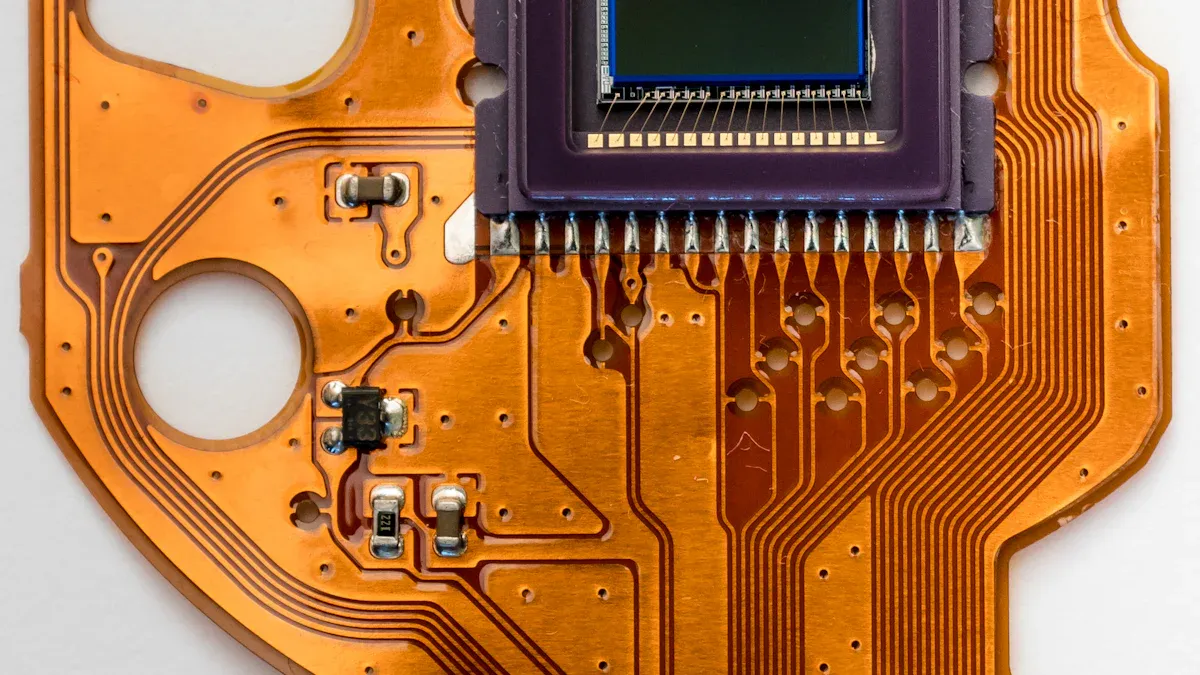
Defect Detection
Defect detection remains a cornerstone of quality assurance in PCB production. Common defects include missing components, extra elements, open circuits, shorts, holes, pattern cuts, pin holes, nicks, and mousebites. Early identification of these defects prevents costly scrap and ensures functional reliability. Leading facilities implement advanced automated optical inspection (AOI) systems that combine high-resolution cameras, 3D imaging, and AI-driven analytics. These systems inspect thousands of solder joints in seconds, achieving detection rates above 99%. AOI systems verify component placement and solder joint integrity, outperforming manual inspection in speed and accuracy. Automating visual inspection not only improves defect detection but also supports real-time process adjustments, reducing the risk of faulty boards reaching the market.
Tip: Regular calibration and skilled programming of AOI systems help address challenges such as complex PCB geometries and minimise false positives, ensuring robust inspection outcomes.
Data and Manpower
Defect Data
Accurate defect data forms the backbone of effective quality control in PCB manufacturing. Manufacturers collect and analyse defect data at every stage, from raw material inspection to final assembly. This data helps identify recurring issues, such as solder joint failures or misaligned components, and enables targeted process improvements. By tracking defect rates and types, teams can prioritise corrective actions and allocate resources efficiently. Data-driven decision-making reduces the risk of undetected defects reaching customers. Regular review of defect trends supports continuous improvement and helps maintain high product standards.
Tip: Consistent data collection and analysis allow manufacturers to spot patterns in defect occurrence, leading to faster root cause identification and resolution.
Skilled Personnel
The demand for skilled personnel in PCB manufacturing remains high. Many fabricators struggle to respond quickly to customer quotes due to limited capacity in quoting departments. Skilled workers play a vital role in managing complex tasks, such as balancing innerlayer stackups and calculating specialty via drill costs. They also adapt to fluctuating material prices and ensure precise measurement during quality checks. Quality control outcomes depend on the capability of measurement systems, which require skilled operators for accurate results. Measurement System Analysis (MSA) evaluates these systems, and skilled personnel conducting MSA help reduce risks and avoid costly errors. Their expertise directly impacts the robustness of quality control and the prevention of defect recurrence.
Training programmes and certifications support skill development. Initiatives like Manufacturing USA focus on workforce development through competency-based learning, apprenticeships, and collaboration with educational institutions. Hands-on courses cover schematic design, PCB layout, and fabrication processes using industry-standard tools. Flexible learning options, such as online batches and weekend classes, make training accessible to a wider audience. These programmes ensure that personnel can address quality issues and minimise defect rates.
Knowledge Retention
Knowledge retention ensures that expertise and best practices remain within the organisation, even as personnel change. Manufacturers document standard operating procedures, defect case studies, and troubleshooting guides. They use digital knowledge bases and regular training sessions to keep teams updated on the latest quality control methods. Peer mentoring and cross-training help transfer skills and reduce the impact of staff turnover. By preserving institutional knowledge, manufacturers maintain consistent quality standards and respond quickly to new issues or defect types.
Note: Strong knowledge retention practices help teams avoid repeating past mistakes and support a culture of continuous improvement.
Rigid and Flexible PCB Adaptability
Scaling Quality Control
Scaling quality control for rigid and flexible pcb production presents unique challenges. Manufacturers must maintain thorough and efficient testing to prevent defect rates that could cause significant losses, especially in mass production of rigid-flex pcbs. Variability in quality often arises from inconsistent processes, making standardised procedures essential. Automation, such as Automated Optical Inspection and functional testing, enables high throughput and consistent inspection, with error rates often below 0.05%. However, automation requires a high initial investment and skilled technicians for operation and maintenance. Manufacturers also face supply chain delays and component shortages, which can halt production. Design errors in prototypes may become costly problems when scaled, so thorough design reviews are vital. Automation supports rapid production and reduces defects, such as cold solder joints, by providing precise temperature control in reflow ovens. Careful planning and workflow redesign help integrate automated systems with minimal disruption, ensuring consistent performance across all pcbs.
Production Line Diversity
Diverse production lines for rigid-flex pcbs demand adaptable quality control strategies. Manufacturers assess capabilities by selecting partners with advanced technologies and automation to ensure precision. They evaluate quality assurance practices, such as ISO 9001 certification, and prioritise value over cost to avoid hidden rework expenses. Lead times and flexibility matter, so manufacturers choose partners who can meet deadlines and adapt to changes without sacrificing quality. Technical expertise and support enhance manufacturability and performance. Effective strategies include running design rule checks, electrical testing, and using Automated Optical Inspection for soldering defects. Manufacturers also manage supply chains closely and validate prototypes before scaling up. Modular fixtures and quick-change stencils enable fast setup and changeovers, supporting a wide range of rigid and flexible pcb products.
Customisation Needs
Customisation in rigid-flex pcbs requires integrated and adaptable quality control systems. Early collaboration with design teams ensures manufacturable and testable assemblies. Agile change management allows quick, controlled engineering changes to handle design modifications. Full traceability through digital tools ensures accountability and regulatory compliance. Manufacturers apply rigorous inspections and real-time monitoring at every stage to maintain quality and performance. Advanced testing platforms, such as flying probe and in-circuit testing, provide comprehensive coverage. Certified technicians uphold high workmanship standards, ensuring consistent results. Quality control systems are tailored to meet industry-specific and customer requirements, supporting continuous improvement and compliance with international standards. This adaptability ensures reliable performance and customer satisfaction in every batch of pcbs.
Manufacturers face persistent challenges in maintaining quality and reliability in rigid and flexible PCB production. Precision, robust data collection, and skilled personnel drive rigorous quality control measures that support long-term performance. Systematic approaches, such as close collaboration during design, advanced inspection tools, and careful documentation, help teams detect defects early and optimise reliability. Regular updates to industry standards and continuous investment in adaptable processes ensure that quality and performance remain high. By prioritising continuous improvement, manufacturers secure both product reliability and customer trust.
Best practices for continuous improvement include:
- Collaborating with manufacturing teams from the design phase.
- Prioritising prototyping and thorough testing.
- Investing in advanced inspection systems.
- Documenting assembly steps and updating processes.
- Staying current with industry standards.
Continuous improvement in quality control measures ensures consistent reliability and long-term performance in every PCB batch.
.png)
.png)
.png)
.png)

.png)

