


 2025-08-07
 BEST
BEST
You can begin learning about flexible integrated circuits by using a step-by-step design process. Each tutorial shows you the important steps in engineering and making them. When you follow a tutorial, you learn how flexible integrated circuits deal with problems like picking materials and handling bending. Making flexible integrated circuits needs careful planning at every step. This tutorial gives you useful tips to help make each circuit strong and dependable.
Key Takeaways
- First, know what your circuit needs to do and decide how flexible it should be, like how much it can bend and how many times. - Pick good materials for the base and wires so the circuit is flexible, strong, and not too expensive. - Plan your circuit layout so there are no sharp bends or places that could break, and keep parts close together with short wires. - Test your circuit early and many times to see if it bends well and works right, so you can find and fix weak spots. - Make your design better by learning from tests and changing small things to help it last longer and work better.
Requirements
Application Needs
Before you start designing, you need to understand what your flexible integrated circuits will do. Think about the main purpose of your project. Will your circuit go into a wearable device, a medical sensor, or a smart label? Each application has its own needs. For example, a medical sensor may need to be very thin and safe for skin contact. A smart label might need to bend around a bottle or package.
You should make a list of all the features your circuit must have. Here are some questions to guide you:
- What size does your circuit need to be?
- How much power will it use?
- What kind of signals will it handle?
- Does it need to connect to other devices?
Tip: Write down your answers. This list will help you make good choices later in the design process.
Flexibility Targets
You also need to decide how flexible your circuit must be. Some flexible circuits need to bend many times without breaking. Others only need to bend once during installation. You should set clear targets for flexibility.
Think about these points:
- Minimum bend radius: How tightly can you bend the circuit without damage?
- Number of bending cycles: How many times will the circuit bend during its life?
- Operating environment: Will the circuit face heat, moisture, or chemicals?
A simple table can help you organize your targets:
| Flexibility Factor | Target Value |
|---|---|
| Minimum Bend Radius | 5 mm |
| Bending Cycles | 10,000 |
| Temperature Range | -20°C to 60°C |
When you set these targets early, you can choose the right materials and design methods. This step makes sure your flexible integrated circuits will work well in real life.
Materials

Substrate Selection
You have to pick the best base for your flexible circuits. The substrate is like the backbone of your design. It keeps all the layers together. It also lets your circuit bend without breaking. Some common choices are polyimide, PET, and PEN. Each one has its own good points.
| Substrate | Flexibility | Heat Resistance | Cost |
|---|---|---|---|
| Polyimide | High | High | Moderate |
| PET | Medium | Low | Low |
| PEN | Medium | Medium | Moderate |
Polyimide is great if you need a lot of flexibility and heat resistance. PET is cheaper and good for easy projects. PEN gives you a mix of price and how well it works. You should pick your substrate based on your flexibility targets and where your circuit will be used.
Tip: Try out small pieces before you choose a substrate. This helps you see how each one bends and handles stress.
Flex Integrated PCB Conductive Materials
You also need to pick the right materials for the electrical paths in your flexible integrated circuits. Copper is used most because it carries electricity well and bends easily. Some projects use silver ink or carbon ink for printed circuits. These are best for low-power or throwaway devices.
- Copper: Strong, dependable, and simple to solder.
- Silver Ink: Good for printing, but costs more.
- Carbon Ink: Cheap and bends well, but not as conductive.
Think about how much current your circuit will need and how often it will bend. If you want high performance, copper is the best choice. For simple or cheap designs, printed inks can save money.
Note: Always make sure your materials fit your application needs and flexibility targets. The right mix helps your flexible circuits last longer and work better.
Flex Integrated Circuits Design
Schematic and Layout
You start your flexible integrated circuits project by creating a clear schematic. The schematic shows how each part connects. You can use design tools like KiCad to draw your circuit. These tools help you place components and draw wires on your computer. When you use a design tool, you can check for mistakes before you build anything.
You should keep your layout simple. Place parts close together if they connect often. Try to keep wires short and avoid sharp turns. This helps your circuit work better and makes it easier to bend. You can use the grid feature in your design software to line up parts neatly. If you plan to use surface-mount devices, make sure you leave enough space for them.
Tip: Save your design often. Use the preview mode in your design tool to see how your circuit will look when finished.
Bend Radius and Stress Points
When you design a flexible circuit, you must think about how much it will bend. If you bend it too much, it can break or stop working. You need to plan for the right bend radius. The bend radius is the smallest curve your circuit can handle without damage.
The table below shows the recommended minimum bend radius for circuits with polyimide substrates:
| Flex Circuit Type | Minimum Bend Radius Recommendation |
|---|---|
| Single-layer flex | At least 6 times the material thickness |
| Two-layer flex | At least 10 times the material thickness |
| Multilayer flex | At least 20 times the material thickness |
For example, if your single-layer circuit uses a polyimide substrate that is 0.1 mm thick, you should not bend it tighter than 0.6 mm. Always use smooth, wide curves instead of sharp bends. This reduces stress and helps your circuit last longer.
You should also look for stress points in your design. These are places where the circuit bends the most or where wires change direction. Try to move important parts away from these areas. You can add extra support or use wider traces in these spots to make your design stronger.
Note: If you need your circuit to bend many times, choose a larger bend radius. This will help prevent cracks and breaks.
Layer Stack-Up
Layer stack-up means how you arrange the different layers in your flexible integrated circuits. You need to plan this carefully. Each layer has a job. The base layer gives support. The conductive layer carries signals. The cover layer protects the circuit from dirt and water.
You can use a single-layer design for simple projects. For more complex circuits, you may need two or more layers. When you add layers, your circuit gets thicker and less flexible. You must balance the number of layers with your flexibility targets.
Here are some steps to plan your stack-up:
- List all the layers you need (base, copper, cover).
- Decide the order of the layers.
- Check the total thickness.
- Make sure the stack-up matches your bend radius needs.
You can draw your stack-up in your design tool. This helps you see how each layer fits together. Good stack-up planning improves mechanical reliability and makes your circuit easier to manufacture.
Tip: Use the thinnest materials that still meet your needs. Thinner circuits bend more easily and last longer.
Integrated Circuit Design Process
VLSI Cycle Adaptation
When you design flexible integrated circuits, you must change the usual VLSI cycle. The VLSI cycle takes your idea and turns it into a real chip. For flexible circuits, you have to think about how it works and how it bends. First, you write down what your circuit should do. Then, you make a block diagram and plan the main parts. Next, you figure out how each part will work together. You use a schematic tool to draw the connections. You also check if your design can bend and flex as needed. In the layout step, you put each part on the flexible base. You need to avoid sharp corners and use smooth lines. This helps your circuit last longer when it bends or stretches.
Tip: Check your design at every step. Early checks help you save time and money.
Data Package Preparation
After you finish your design, you must make a data package for building. This package has all the files and papers needed to make your flexible circuit. You should include the schematic, layout files, bill of materials, and assembly drawings. Add notes about bend radius and special care.
Here is a simple checklist for your data package:
- Schematic diagram
- Layout files (Gerber or ODB++)
- Bill of materials (BOM)
- Assembly instructions
- Mechanical drawings
- Flexibility notes
You send this data package to your manufacturer. Clear and full files help stop mistakes during building. Good planning makes the build easier and gives better results for your integrated circuit design.
Fabrication
Patterning Methods
You need to use careful patterning methods to make flexible integrated circuits. These methods help you create tiny, detailed shapes on your circuit. Here are some of the best ways:
- Laser Direct Imaging (LDI): This method uses a laser to draw patterns right onto your circuit. LDI is very exact and can make features as small as 15 micrometers. You do not need masks, so you do not have to worry about lining things up wrong. LDI is good for flexible materials because it does not use much heat or pressure.
- Advanced Photoresist Materials: These special photoresists stick well to flexible bases. They help you make lines smaller than 20 micrometers. These materials also work on thin or bumpy surfaces.
- Specialized Handling Equipment: You can use vacuum tables or roll-to-roll systems to keep your circuit flat while you work. These tools stop the material from moving or stretching. This keeps your patterns neat and correct.
- High-Resolution Additive Techniques: Inkjet printing puts conductive ink exactly where you want it. This method can make features smaller than 30 micrometers. It is great for very thin and bendy circuits.
- Best Practices: Keep your work area at the same temperature and humidity. Use simulation software to find problems before you start. Test your process often to get the best results.
Tip: Always look at your patterns with a microscope. Small mistakes can turn into big problems later.
Lamination and Layering
You build your flexible circuit by adding layers one at a time. Each layer has its own job. The base layer gives support. The conductive layer carries signals. The cover layer keeps out dirt and water.
You start by putting the base layer on a flat surface. Next, you add the conductive layer using your patterning method. After that, you put on the cover layer. You use heat and pressure to stick the layers together. This is called lamination.
You must keep the layers lined up during lamination. If the layers move, your circuit might not work. Use alignment marks and handle everything carefully to keep it in place. Some factories use roll-to-roll machines to make lots of circuits at once. This saves time and keeps the layers even.
Note: Thin layers bend more easily but can be weaker. Pick your layer thickness based on how much your circuit needs to bend and how strong it should be.
Assembly
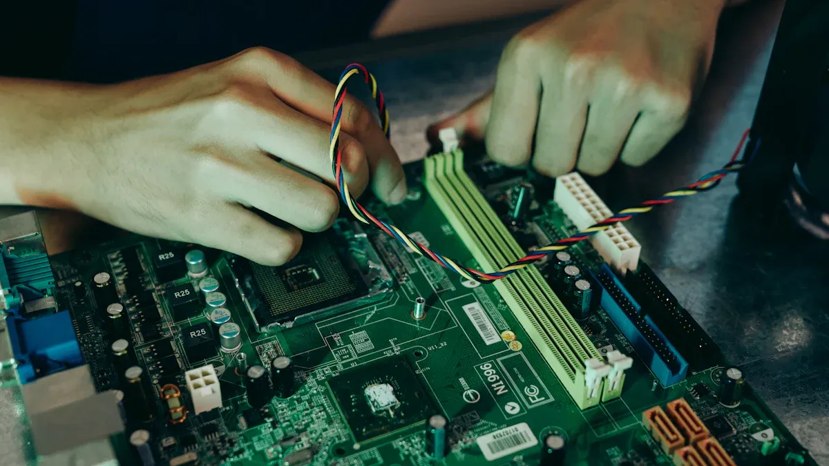
Component Placement
You have to put each part on your flexible integrated circuit carefully. First, look at your layout plan. Make sure you know where every part should go. Use tweezers or a pick-and-place machine for tiny parts. Put heavy or breakable parts on flat spots. This helps your circuit bend without breaking.
Try not to put parts where the circuit will bend a lot. If you must put a part near a bend, give it extra support. You can use stiffeners or glue to hold parts in place. Always check that each part faces the right way before you solder it.
Tip: Make a checklist to keep track of each part as you place it. This helps you avoid mistakes and saves time when you build your circuit.
Here is an easy checklist you can use:
- Check the part number
- Make sure it goes in the right spot
- Place the part gently
- Hold the part in place if needed
Interconnects and Encapsulation
You need to connect all the parts with strong and bendy interconnects. Use flexible wires or printed traces for these connections. Make sure each connection can bend without breaking. Solder joints should be smooth and not too thick. If you use connectors, pick ones made for flexible circuits.
Encapsulation keeps your circuit safe from water, dust, and damage. You can use silicone, epoxy, or special flexible coatings. Put the encapsulation on in thin layers. Cover all the parts and traces that show. Let each layer dry before you add another one.
Note: Good encapsulation keeps your circuit safe and working longer. Test your circuit after you cover it to make sure it still works.
A table can help you pick the best encapsulation material:
| Material | Flexibility | Protection Level | Use Case |
|---|---|---|---|
| Silicone | High | Medium | Wearables |
| Epoxy | Low | High | Rigid sections |
| Polyurethane | Medium | High | Outdoor devices |
You should always match your assembly steps to your flexibility targets. Careful assembly helps your flexible integrated circuits last longer and work better.
Testing
Mechanical Validation
You need to check if your flexible integrated circuit can handle bending and stretching. Start by gently bending your circuit to the minimum bend radius you set earlier. Watch for cracks or changes in shape. If you see any damage, your design may need more support or a different material.
You can use a simple test to count how many times your circuit bends before it fails. Bend the circuit back and forth. Keep track of each cycle. Many engineers use a machine for this, but you can do it by hand for small projects. Write down the number of cycles your circuit survives.
Tip: Use a magnifying glass to look for tiny cracks after testing. Small cracks can grow and cause problems later.
A table can help you record your results:
| Test Type | Result |
|---|---|
| Bend Radius Test | Passed/Failed |
| Cycle Test | Number of Cycles |
| Visual Check | Cracks/No Cracks |
Electrical Testing
After you finish mechanical tests, you must check if your circuit still works. Use a multimeter to measure resistance across the traces. Low resistance means good connections. High resistance or no reading means a break in the circuit.
You should also power up your circuit and see if all parts work as planned. Test each function one by one. If you find a problem, check the solder joints and traces for damage.
- Measure voltage at key points.
- Check signal paths with an oscilloscope if you have one.
- Test the circuit while bending it gently to see if it keeps working.
Note: Always test your circuit both before and after bending. This helps you find weak spots early.
Optimization
Iteration Steps
You can improve your flexible integrated circuits by following a clear development cycle. Start by testing your first version. Write down what works and what does not. Use this feedback to make changes. You might need to adjust the layout, pick new materials, or change the bend radius. Each time you make a change, build a new prototype. Test it again. This process helps you find problems early.
A simple iteration cycle looks like this:
- Build your first prototype.
- Test for both mechanical and electrical performance.
- Record all results and issues.
- Change your design based on what you learn.
- Repeat the development steps until you reach your goals.
Tip: Keep a logbook for each round of development. This helps you track what changes lead to better results.
Performance Refinement
You can make your flexible integrated circuits work better by focusing on small details. Check if your circuit bends as much as you want. Make sure it does not break after many cycles. If you see weak spots, try using stronger materials or changing the trace width. You can also improve signal quality by shortening traces and using better shielding.
Use a table to compare each version:
| Version | Bend Cycles | Signal Loss | Notes |
|---|---|---|---|
| V1 | 5,000 | High | Needs stronger base |
| V2 | 10,000 | Medium | Improved traces |
| V3 | 15,000 | Low | Best performance |
You should always aim for the best mix of flexibility and reliability. Small changes in your design can lead to big gains in performance. Keep testing and refining during development. This approach helps you create circuits that last longer and work better in real-world use.
Challenges
Material Fatigue
Material fatigue is a big problem for flexible integrated circuits. If you bend your circuit many times, copper traces and glue layers can wear out. This can make cracks or breaks appear. Many things affect how long your circuit will last:
- Bend radius: A bigger bend radius helps stop copper from cracking.
- Copper thickness and type: Thinner copper bends better but can raise resistance. Rolled-Annealed (RA) copper is best for circuits that bend a lot.
- Trace routing: Put traces across bend lines and do not use vias in places that bend a lot.
- Adhesive selection: Adhesiveless polyimide-copper bonding or low outgassing epoxy glue lasts longer, even in tough places.
- Strain relief: Use curved traces, mesh shapes, or stiffeners to lower stress.
You should always test your design by bending it thousands of times. This helps you find weak spots before you use the circuit for real.
Tip: Make your minimum bend radius at least 10 times the total thickness of your circuit. This helps your circuit last longer.
Signal Integrity
Signal integrity can be a problem when your circuit bends or stretches. Bending can change the shape of traces and cause signal loss or noise. You can keep signals strong by:
- Using short, wide traces to lower resistance.
- Keeping traces away from places that bend a lot.
- Adding shielding layers if your circuit has fast signals.
- Testing your circuit while bending to check for signal drops.
If you see signal problems, try changing the trace layout or use better materials.
Manufacturability
Making flexible integrated circuits can be hard. Flexible materials can stretch or move during making. This can cause layers to not line up or traces to break. To make manufacturing better, you should:
- Use alignment marks to keep layers lined up.
- Pick materials that handle heat and pressure well.
- Work with manufacturers who know flexible circuits.
- Test small batches before making a lot.
Note: Careful planning and clear instructions help you avoid costly mistakes when making your circuits.
You now know the main steps to design flexible integrated circuits. Every step, like planning and testing, helps your circuits work well and last longer.
- Flexible circuits help you make medical devices you can wear. These devices fit the body and check your health.
- New materials such as polyimide keep devices safe and comfy on your skin.
- Good design makes your circuits strong and correct, even after lots of bending.
Keep learning and try out new tools. Your ideas can help make better electronics for all people.
.png)
.png)
.png)
.png)

.png)

