


 2026-02-26
 BEST
BESTTable of Contents
- What Is Alignment Accuracy and Why It Matters for Rigid-Flex PCB
- US Design Standards & Tolerance Benchmarks for Rigid-Flex PCB Alignmen
- Key US Sectors and Their Alignment Precision Requirement
- Engineering Factors Influencing Rigid-Flex Alignment Accurac
- Best Practices for Achieving High Alignment Accuracy in Manufacturin
- FAQ — Alignment Accuracy of Rigid-Flex PCBs
- Why BESTFPC Is the Precision Supplier for Rigid-Flex Solutions
- Conclusion: Design to Delivery for High-Accuracy Rigid-Flex PCBs
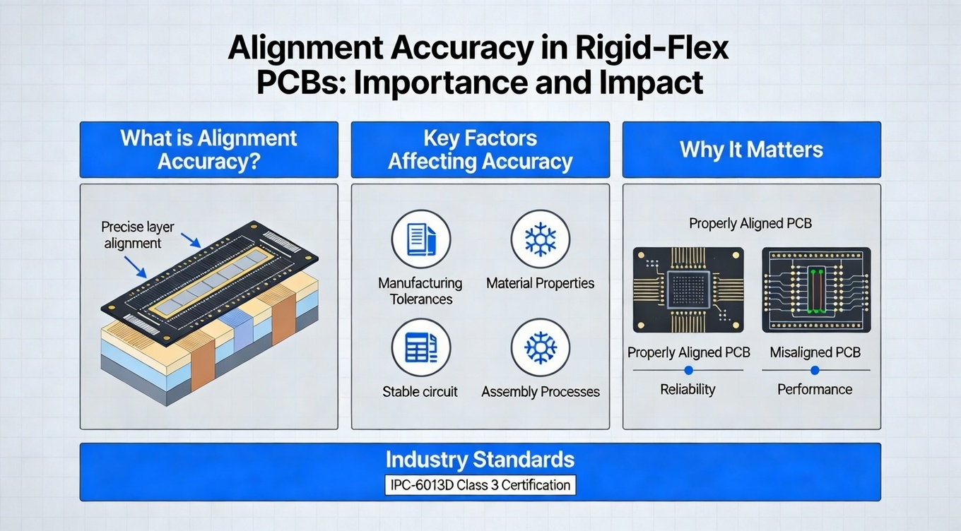
What Is Alignment Accuracy and Why It Matters for Rigid-Flex PCBs
Alignment accuracy of a rigid-flex PCB refers to how precisely the rigid and flexible layers, drill features, and circuit traces align during lamination and subsequent process steps. This precision ensures that electrical paths cross layer boundaries without distortion, maintain impedance integrity, and support mechanical performance over multiple flex cycles.
In the USA, the importance of alignment accuracy stems from its direct influence on electrical performance, signal integrity, and long-term reliability — especially in sectors like aerospace, automotive, and medical where failure is not an option. Misalignment at the micron level can lead to trace offsets, short circuits, intermittent connections, and reduced product life.
Definition of Alignment Accuracy
Alignment accuracy is evaluated by how closely the actual physical layer registration matches the design intent. This is typically measured in micrometers (µm) or mils (thousandths of an inch). For advanced rigid-flex designs, target alignment tolerances are often ±25–50 µm for high-density interconnects, though specific tolerance targets vary by application and reliability class.
How Misalignment Impacts Functionality
When rigid and flex regions do not align accurately, the following problems can occur:
- Electrical Discontinuities: Misaligned vias and traces may not make reliable contact, leading to intermittent opens or shorts.
- Impedance Disruption: In high-speed designs, misalignment alters trace geometry and impedance, degrading signal integrity.
- Mechanical Weak Points: Stress concentrations appear where layers are offset, leading to delamination or fatigue under flex cycles.
For US system integrators — especially in safety-critical domains — alignment accuracy is a design requirement rather than a manufacturing convenience.
Internal Link Idea (from Google Search Console high-engagement pages):
Use anchor texts like “Rigid-Flex PCB Capabilities”, “High-Density PCB Manufacturing Details”, and “PCB Alignment & Metrology Techniques” to link to high-traffic internal content at strategic points in this section.
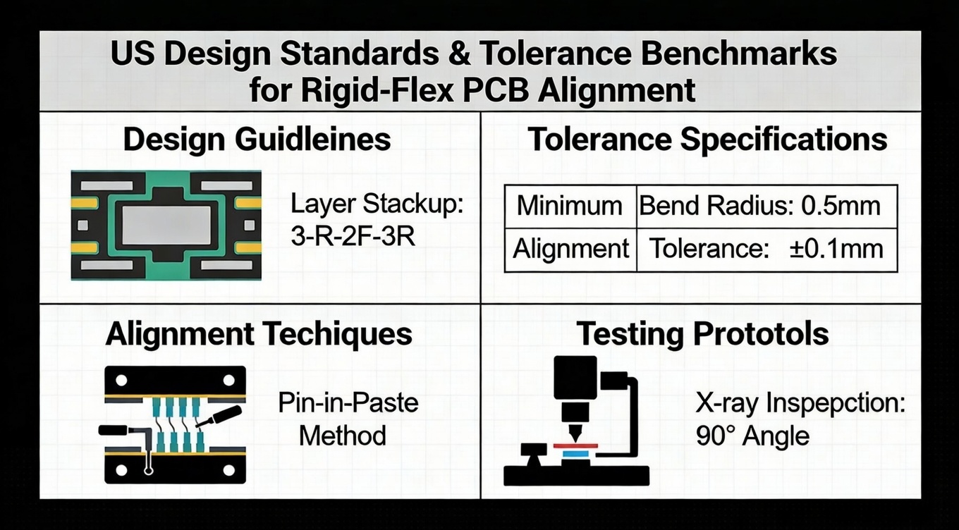
US Design Standards & Tolerance Benchmarks for Rigid-Flex PCB Alignment
Rigid-flex PCB alignment is not covered by a single US government standard, but the industry relies on widely accepted design and quality standards that influence what acceptable tolerances should be.
IPC Tolerance Guidelines
The IPC standards relevant to rigid-flex include:
- IPC-6013: Qualification and performance specification for flexible and rigid-flex PCBs — defines performance classes and acceptance criteria.
- IPC-2223: Design standard for flexible printed boards — provides guidelines for trace geometry, via placement, and suggested tolerances.
- IPC-6012 / 6018: Referenced when components demand hybrid rigid-flex performance criteria aligned with high reliability.
For US aerospace and defense integrators, alignment accuracy expectations often align with Class 3 (High Reliability) IPC performance levels, where tighter registration tolerances are expected and verified through meticulous inspection protocols.
Industry-Specific Variation Requirements
Different sectors drive tighter or looser tolerances. For instance:
- Medical implants and diagnostics may require tighter than ±25 µm alignment for ultra-low noise signal paths.
- Automotive systems prioritize robust mechanical alignment that survives vibration and thermal cycling rather than minimal distance tolerances alone.
- Communication board assemblies such as high-speed RF modules demand precise alignment to maintain impedance matching.
Understanding these benchmarks helps designers frame realistic expectations for fabrication capability and performance outcomes.
Key US Sectors and Their Alignment Precision Requirements
Alignment accuracy is not equally critical in all applications. Below we examine how major US industries define their requirements:
Aerospace & Defense
In aerospace electronics — both commercial and defense — alignment precision directly affects failure rates under extreme vibration and temperature cycles. Controlled alignment ensures that high-reliability systems perform predictably over mission lifetimes. Quality systems here often mandate Class 3 IPC conformance and rigorous inspection records.
Medical Devices & Wearables
Medical systems such as imaging, diagnostic platforms, and patient monitoring devices often operate in environments where signal integrity is essential. Misalignment can compromise analog and digital signal paths, leading to degraded performance or inaccurate readings. This drives tighter alignment controls and verification procedures.
Automotive & ADAS
Advanced Driver Assistance Systems (ADAS), electric vehicle controls, and power electronics use rigid-flex boards to save space and improve reliability. Alignment precision must accommodate repeated flexing, thermal cycling, and vibration — all within safety-critical automotive standards. This results in design rules that emphasize mechanical registration stability over time.
High-Speed Communications & Servers
High-frequency communication systems rely on precise trace geometry and controlled impedance. Misaligned layers affect differential pair routing, increasing insertion loss and signal reflection — unacceptable in high-speed data applications.
Engineering Factors Influencing Rigid-Flex Alignment Accuracy
Achieving tight alignment accuracy in rigid-flex manufacturing requires attention to several engineering and process variables:
Material Properties & CTE
Rigid and flex materials (FR4 + polyimide) have differing coefficients of thermal expansion (CTE). During lamination and thermal cycling, these mismatched expansion rates can shift layer registration. Precise control of heat profiles and material selection reduces differential movement.
Lamination & Registration Technology
Modern rigid-flex fabrication uses laser registration systems and automated alignment fixtures. These systems measure fiducials on each layer, automatically correcting offsets before lamination. Advanced fabrication lines can reliably hold alignment tolerances of ±25–50 µm under controlled conditions.
Inspection & Metrology Tools
Automated Optical Inspection (AOI), X-ray imaging, and Coordinate Measurement Machines (CMM) provide post-process validation of alignment accuracy. In US high-reliability applications, alignment results are recorded and included in quality documentation delivered with each shipment.
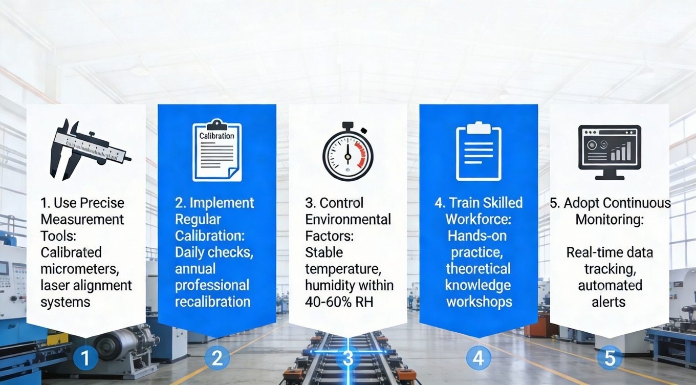
Best Practices for Achieving High Alignment Accuracy in Manufacturing
Manufacturers aiming for high alignment precision implement several best practices:
Process Controls & QA Systems
Structure rigorous process control documents that track temperature profiles, lamination pressures, and etching tolerances. High-maturity factories use Statistical Process Control (SPC) to limit variation.
Automated Optical & Laser Registration
Both face and internal layers are pre-aligned using automated systems that reference laser-etched fiducials. This minimizes human error and enables repeatable results at scale.
Feedback for Design for Manufacturability (DFM)
During design reviews, feedback helps engineers adjust layouts — e.g., spacing overlapping regions, adjusting drill tolerances, and optimizing stack-ups — which improves final alignment controllability.
Internal Link Suggestions:
Use high-click anchors like “PCB Alignment Techniques”, “Advanced PCB Metrology Tools”, and “Rigid-Flex PCB Capabilities” linked to corresponding internal pages to improve crawl depth.
FAQ — Alignment Accuracy of Rigid-Flex PCBs
Q1: What typical alignment tolerances are achievable in rigid-flex PCBs?
Advanced fabrication lines can reliably achieve ±25–50 µm alignment tolerances depending on stack-up and material combination.
Q2: Why is alignment accuracy more critical in rigid-flex vs rigid PCBs?
Rigid-flex boards experience dynamic stress and layer transitions that amplify misregistration effects on electrical and mechanical performance.
Q3: Does higher alignment precision increase cost?
Tighter alignment goals may require advanced tooling and inspection but ultimately reduce field failures and warranty costs — a key consideration in high-reliability applications.
Why BESTFPC Is the Precision Supplier for Rigid-Flex Solutions
BESTFPC combines global engineering expertise with manufacturing precision tailored for US markets:
- Industry-aligned process controls and quality documentation
- Laser registration and AOI systems supporting high alignment accuracy
- Engineering support for DFM, stack-up planning, and reliability verification
- Capability to deliver multi-layer FPCs and rigid-flex boards with stringent tolerance requirements
Our team works collaboratively with US design engineers to anticipate alignment challenges early in the design phase, reducing iteration cycles and improving delivery predictability.
Conclusion — Design to Delivery for High-Accuracy Rigid-Flex PCBs
Alignment accuracy is a defining factor in rigid-flex PCB performance, especially in demanding US industries like aerospace, automotive, medical, and high-speed communication. Understanding tolerance benchmarks, process capabilities, and design factors is essential for engineering success.
By partnering with a supplier like BESTFPC, US buyers gain access to advanced manufacturing controls, rigorous quality systems, and design collaboration — all critical to achieving alignment accuracy goals and delivering reliable products to market.
.png)
.png)
.png)
.png)

.png)

