


 2022-11-08
 BEST
BESTSection: 1. The minimum line/trace widths and thicknesses of the finished FPC wire shall be determined by the required current carrying capacity of the wire and the maximum allowable temperature rise.
Section: 2. The Minimum line width/space at BEST TECH currently is 2mil/2mil (0.05/0.05mm)
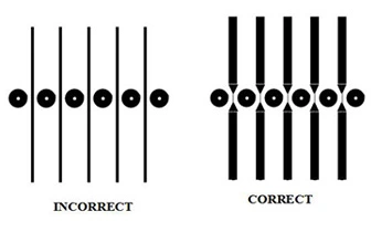
Section: 3. As for the circuits in the hollow zone of the single side double head and hollow board (Duall Access FPC) as well as double side hollow board are better designed to be wider for avoiding disconnection due to insufficient strength during the fabrication process.
Takeaway: The thickness and width of flexible circuit board are determined by its current carrying capacity, temperature rise and strength to against sever processing procedures like punching, bending, testing, etc..
Maximizing Line Widths
You can find some simple calculators to calculate the trace (conductor) width for circuit board:
PCB Trace Width Calculator 1: Based on a curve fit to IPC-2221 (formerly IPC-D-275);
Inter PCB Trace Width Calculator;
External PCB Trace Width;
Inter PCB Trace Max Current;
External PCB trace Max Current;
Trace Resistance;
The Line Space Design
The first thing to consider is the electrical characteristics. The line space on each layer should be as larger as possible to meet the requirement of the rated voltage between the wires. There is a table for your reference as below:
.png)
.png)
.png)
.png)

.png)

