


 2022-11-08
 BEST
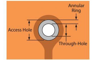
BESTAlthough squeeze-out only affects external layers, internal annular rings in rigid-flex circuit and multi-layer flex are often compromised, especially in places where tight hole to pad ratios are demanded. This is mainly due to the dimensional stability (1000ppm) of the flexible material. It is common to allow zero breakouts ( ) of the hole from the internal pad, and on some commercial parts there is sometimes agreement to allow a 270° minimum contact ring.
When designing flexible printed circuits, allows for some misregistration between the internal pads and the drilled hole, and consider minimum space between the traces and the drilled holes.
Allow the use of a larger hole tolerance than is specified for external connectors.
Keep in mind that minimum space between the traces and the drilled holes is always a critical factor.
Plating Flex Circuit Boards
For double-sided flexible products we can use a selective plating process “pads only plate” to plate copper in the through-holes. In order to accomplish this, we drill the flexible copper clad dielectric material and then image the “pads plate” image around the drilled holes at (drilled diameter) D + .003” or better. After plating the holes with approximately .0004” (10um) of copper we image again with the finished circuitry pattern and the etch the desired pattern. An additional D + .014” of pad is needed for this etching process, which puts our minimum pad size on double-sided flexible products at a drilled diameter + .017.” These pads should always be as large as your design will allow.
|
Layer Type |
Standard (mils) |
Advanced (mils) |
|
Flex |
Drill + 14 |
Drill + 10 |
|
Outer Layer Rigid |
Drill + 10 |
Drill + 6 |
|
Inner Layer Rigid |
Drill + 14 |
Drill + 10 |
.png)
.png)
.png)
.png)

.png)

