


 2025-08-29
 BEST
BEST
When I design complex flex PCB solutions for automotive converters, I face demanding challenges. I always optimize the stack-up and select materials that withstand thermal expansion and harsh environments. For every flex pcb, I prioritize compliance with automotive standards and focus on reliability, manufacturability, and performance. I rely on these core principles because flexible circuit boards must endure mechanical stress and maintain signal integrity. The table below highlights the most common hurdles in flexible printed circuit boards for automotive applications:
| Challenge | Description |
|---|---|
| Complex Design Rules | Rigid-flex PCBs require understanding both mechanical and electrical needs. |
| Bend Radius Considerations | Choosing the right bend radius prevents failure and signal issues. |
| Material Selection | Proper materials avoid reliability problems from thermal expansion. |
| Signal Integrity and EMI | Maintaining signal quality in flexible sections is challenging. |
| Connector Placement | Proper placement avoids mechanical stress. |
| Layer Transition | Correct signal layer transitions prevent impedance mismatches. |
| Thermal Management | Heat dissipation is more complex in rigid-flex designs. |
| Assembly and Manufacturing | Assembly requires careful component placement. |
| Testing and Inspection | Specialized equipment is often needed for testing. |
| Mechanical Reliability | Flexible sections must withstand repeated bending. |
| Cost | Manufacturing costs rise with design complexity. |
| Design for Manufacturability | Good manufacturability needs close collaboration with fabricators. |
| Environmental Factors | Harsh automotive conditions require extra care in design. |
| Design Verification | Rigorous testing ensures specifications are met. |
With experience in flex pcb design, I know that every step impacts the final product’s durability and functionality.
Key Takeaways
- Start flex PCB design by defining specifications and functional needs. This helps avoid costly changes later.
- Select materials like polyimide for durability and flexibility. Proper material choice enhances reliability in harsh environments.
- Optimize stack-up design to handle electrical, thermal, and mechanical stress. This ensures long-term performance and manufacturability.
- Follow best practices for routing and bend radius. This maintains signal integrity and mechanical reliability in flex PCBs.
- Conduct thorough testing and quality control. This guarantees that the final product meets all automotive requirements.
Automotive Flex PCB Requirements

Reliability & Environmental Factors
I always start my flex pcb design by considering reliability. Automotive converters operate in environments with high vibration, temperature swings, and exposure to moisture. I select flexible circuit materials that resist thermal expansion and mechanical stress. Polyimide stands out for its heat tolerance and flexibility. I focus on the fabrication process to ensure every flex pcb can withstand repeated bending and harsh conditions. I work closely with my team to test each flex pcb for durability before moving to mass fabrication.
| Standard | Purpose |
|---|---|
| ISO 26262 | Functional safety |
| IATF 16949 | Quality management in automotive manufacturing |
| IPC-6012DS | High-reliability rigid PCBs |
| AEC-Q200 | Standards for passive components |
I always verify that my flex pcb meets these standards. This step guarantees reliability and safety in every automotive application.
Compactness & 3D Design
I design flex pcb layouts to maximize compactness. Space inside car converters is limited. I use 3D integration to fit circuits into tight spaces. My approach includes:
- Choosing flexible circuit materials like polyimide for durability and flexibility.
- Optimizing via placement to improve reliability and flexibility.
- Designing for manufacturability so the fabrication process remains efficient and cost-effective.
I see flex pcb technology in dashboard displays, entertainment systems, and advanced driver-assistance systems. Compact designs help me reduce weight and improve performance.
Standards & Compliance
I never overlook compliance in flex pcb design. Automotive converters must meet strict standards. I follow ISO 26262 for functional safety and IATF 16949 for quality management. I use IPC-6012DS for high-reliability rigid PCBs and AEC-Q200 for passive components. I document every step of the fabrication process to ensure traceability. My team and I review each flex pcb for compliance before starting mass fabrication. This approach helps me deliver reliable products that meet global automotive requirements.
Design Complex Flex PCB: Key Steps
Define Specs & Functional Needs
When I start to design complex flex pcb for car converters, I always begin by defining the specifications and functional needs. I gather all requirements from the automotive system, including voltage, current, and signal types. I look at the space available for the flex pcb and note any mechanical constraints. I also consider how the flexible circuit boards will interact with other components. This step helps me avoid costly changes later in the design process.
I create a checklist for each flex pcb design:
- List all electrical and mechanical requirements.
- Identify the number of layers needed for the circuit.
- Determine the type of connectors and their placement.
- Specify the expected bending cycles and minimum bend radius.
- Note any special needs for thermoformed flex pcb or advanced processes in thermoformed flex pcbs.
By setting clear specs, I make sure the flex pcb will meet both performance and reliability targets. This approach also helps me communicate better with my team and the fabrication partner.
Pre-Layout & Modeling
Before I move to the layout stage, I always perform detailed modeling. I use simulation tools to predict how the flex pcb will behave under real-world conditions. I check for signal integrity, EMI, and thermal performance. I follow IPC standards to guide my flex circuit design and ensure the design process meets industry best practices.
I often build a 3D model of the flex pcb. This model helps me visualize how the flexible circuit boards will fit inside the converter. I can spot potential issues with bend radius or connector placement early. I also use the model to test different stack-up options and see how they affect flexibility and reliability.
Tip: Early modeling saves time and reduces errors during fabrication. I always recommend sharing these models with the fabrication team to get feedback before finalizing the design.
I also run tests on prototypes. I use these tests to validate the design process and make sure the flex pcb meets all specs. This step is critical for advanced processes in thermoformed flex pcbs, where the shape and flexibility must match exact requirements.
Stack-Up & Materials
Stack-up optimization is one of the most important steps in flex pcb design. The right stack-up ensures the flex pcb can handle electrical, thermal, and mechanical stress. I select materials that match the needs of automotive converters and support the design complex flex pcb process.
Polyimide is my go-to material for flexible circuit boards. It offers excellent flexibility, thermal stability, and chemical resistance. I often choose adhesiveless constructions for high-speed or dynamic flex applications. These materials reduce thickness and improve the flex pcb’s dynamic performance. Ultra-thin flex pcb materials are also becoming popular for automotive designs because they provide better dimensional stability and controlled dielectric properties.
The stack-up design directly affects the reliability and manufacturability of the flex pcb. I always review the stack-up with my fabrication partner to ensure it meets both electrical and mechanical needs. Here is a typical stack-up table I use for automotive flex pcb projects:
| Layer | Dielectric Material | Thickness |
|---|---|---|
| Top solder | Solder mask | 0.018mm |
| Top layer | TU768 | 0.046mm |
| Layer 2 | TU768 core + PP | 0.406mm |
| Layer 2 | NON FLOW TU84P | 0.064mm |
| Flex top coverlay | FC-001 | 0.051mm |
| Layer 3 | PP-006 | 0.076mm |
| Layer 4 | BT25X2 | 0.051mm |
| Bottom coverlay | FC-001 | 0.051mm |
| Rigid layers | Non FLOW TU84P | 0.064mm |
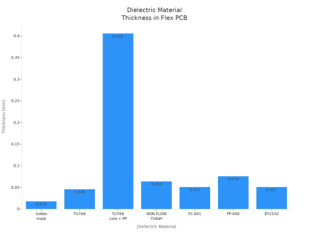
I always check the thickness of each layer to balance flexibility and strength. The right combination of flex pcb materials ensures the board can survive harsh automotive environments. I also pay attention to the fabrication process, making sure each material is compatible with the chosen stack-up.
Note: The design process for a thermoformed flex pcb often requires special materials and stack-up arrangements. I work closely with suppliers to source the best flex pcb materials for each application.
By following these steps, I can design complex flex pcb solutions that meet the strict demands of automotive converters. I always focus on reliability, manufacturability, and performance at every stage of the design process.
Flex PCB Design Best Practices
Schematic & Layout
When I design a flex pcb for automotive converters, I always start with a clear schematic. I map out every connection and component, making sure the circuit meets all functional requirements. I pay close attention to the placement of high-power and sensitive components. I know that strategic placement reduces trace lengths and helps avoid thermal interference. I use solid power and ground planes to minimize electromagnetic emissions and prevent board warping. I always ensure that trace widths match the required current load, which prevents overheating and improves reliability.
I incorporate thermal reliefs and vias to dissipate heat efficiently. I add copper pours and heat sinks around high-power components. This approach keeps the flex pcb cool during operation. I space traces generously to prevent electromagnetic coupling and minimize crosstalk. I avoid routing signal traces parallel to each other, which reduces mutual inductance and improves signal integrity.
Tip: I always distribute high current loads across multiple vias. This lowers resistance and helps the flex pcb handle demanding automotive environments.
Routing & Bend Radius
Routing is one of the most critical steps in flex pcb design. I follow best practices to ensure both electrical performance and mechanical reliability. I use 135-degree bends instead of sharp 90-degree angles. This reduces signal reflections and avoids creating sharp edges that can act as antennas. I always match each segment of a differential pair connection individually. This ensures synchronous signal propagation and maintains signal quality.
Here is a table of routing and bend radius best practices I follow:
| Best Practice | Description |
|---|---|
| Bends Compensation | Two bends compensate for each other. If bends are closer than 15mm, no extra compensation is needed. |
| Differential Pair Matching | Match each segment of a differential pair for synchronous signal propagation. |
| Bend Angles | Use 135° bends instead of 90° to avoid etching issues and reduce EMI. |
| Trace Width Distance | Keep at least 4x the trace width between adjacent copper; each bend segment is 1.5x the trace width. |
| Loop Inclusion | Use small loops for shorter traces if space allows, which is often better than serpentine traces. |
I always optimize the bend radius to maintain the mechanical integrity of the flex pcb. I follow these guidelines:
- I keep the minimum bend radius at least six times the material thickness for single-layer flex pcb designs.
- For two-layer flex pcb circuits, I increase the minimum bend radius to ten times the thickness.
- In multilayer flex pcb designs, I use a minimum bend radius of twenty times the thickness.
- I avoid sharp bends and creases because they create high-stress points. Over time, these can cause material fatigue, cracking, or delamination.
By following these rules, I ensure the flex pcb maintains its flexibility and survives repeated bending in automotive converters.
EMI & Thermal Management
Electromagnetic interference (EMI) and thermal management are top priorities in every flex pcb project I handle. I use several strategies to control EMI and keep the circuit stable:
- I use metallic shielding around sensitive circuits to contain EMI.
- I implement proper ground planes to reduce EMI and avoid ground loops.
- I add low-pass filters, decoupling capacitors, and ferrite beads to attenuate high-frequency signals.
- I select components that minimize EMI generation.
- I sometimes adjust software settings to help manage EMI effects.
For thermal management, I always use thermal reliefs and vias to dissipate heat. I place copper pours and heat sinks near high-power components. I route high-speed signals over solid ground planes to maintain consistent impedance and reduce thermal buildup. I also ensure that trace widths are appropriate for the current load, which prevents overheating.
Note: I always review the fabrication process with my manufacturing partner. This ensures that all EMI and thermal management strategies are compatible with the chosen materials and stack-up.
By following these best practices, I improve both the manufacturability and performance of every flex pcb I design. I always collaborate closely with the fabrication team to ensure the fabrication process delivers reliable results for automotive converters.
Verification & Production
Mechanical Review
I always begin the verification process with a thorough mechanical review. I check every flex pcb for proper fit and alignment within the car converter enclosure. I inspect the bend areas and confirm that the stack-up supports repeated flexing without cracking. I look for signs of stress at connector points and rigid sections. My team and I use 3D models to simulate installation and movement. This step helps me catch mechanical issues before fabrication starts. I work closely with the flex pcb manufacturer to ensure that the design matches the production capabilities. I pay special attention to the layer count and mechanical support, since these factors affect both durability and cost.
Testing & Quality Control
Testing and quality control are critical for every flex pcb project. I follow strict standards to guarantee reliability and safety. I use IPC-6013 and IPC-A-600 to check the performance and acceptability of each flex pcb. I require UL certification for flammability and ISO 9001 for quality management. My team runs electrical tests and visual inspections after fabrication. We use specialized tools to test for signal integrity and thermal performance. Testing flex pcbs takes more time and resources than rigid boards. I know that accessing components for repair is difficult, so I focus on getting it right the first time. Here is a table of common production challenges I encounter:
| Challenge | Description |
|---|---|
| Low Durability | Flex PCBs can be damaged due to excessive bending, folding, or twisting, requiring careful handling. |
| Complexity in Repairs | The flexibility of flex PCBs makes repairs difficult, as accessing components is challenging. |
| Limitation in Component Installation | Heavy components are limited due to concerns about mechanical durability and stress on the PCB. |
| Limited Layer Count | Flex PCBs typically have a layer count of 1 to 6, affecting overall functionality compared to rigid PCBs. |
| Testing Challenges | Testing flex PCBs is more time-consuming and expensive, requiring traditional methods and suitable tools. |
I always document every test result and share it with the flex pcb manufacturer. This process ensures that the final product meets all automotive requirements.
Manufacturing Readiness
Before I approve a flex pcb for mass production, I review the entire fabrication process. I check that all materials and stack-ups are available and compatible with the chosen design. I discuss cost factors with the flex pcb manufacturer, including layer count, material selection, and surface treatment. I know that each additional two layers can increase costs by up to 40 percent. I choose materials and treatments that balance quality and budget. I also consider mechanical support, such as flexible arms ending in rigid sections, to reduce costs. Here is a table of quality assurance standards I use during production:
| Standard | Description |
|---|---|
| IPC-6013 | Performance specification for flexible PCBs |
| IPC-A-600 | Acceptability of printed boards |
| UL Certification | Safety and flammability testing |
| ISO 9001 | Quality management systems |
I always communicate with the flex pcb manufacturer to confirm readiness for mass fabrication. I verify that all documentation is complete and that the production line can handle the complexity of the flex pcb design. This approach helps me deliver reliable, high-quality flex pcbs for automotive converters in Turkey and beyond.
Designing complex flex PCBs for car converters requires careful planning at every stage. I always focus on stack-up and material selection because these choices impact signal integrity, heat management, and long-term reliability.
- Proper stack-up design maintains performance and electromagnetic compatibility.
- The right materials improve dielectric properties and thermal behavior.
- I recommend using conductive shields, coatings, and gaskets for EMI protection. For deeper learning, I explore advanced resources on EMI shielding and thermal management in automotive flex PCB design.
.png)
.png)
.png)
.png)

.png)

