


 2025-07-22
 BEST
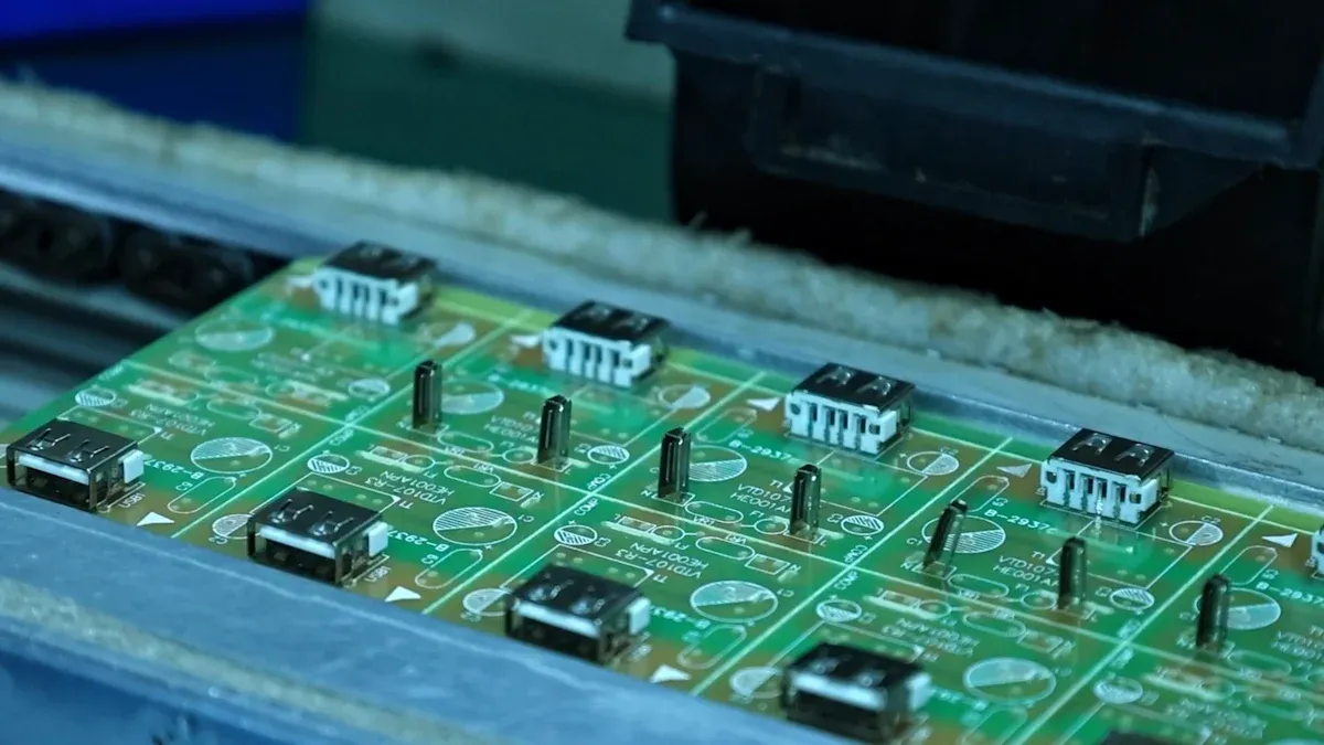
BESTA flexible printed circuit (FPC) substrate forms the foundation of a flexible PCB, providing both structure and electrical insulation. The choice of fpc substrate directly impacts flexibility, durability, and overall performance in electronic devices. The global demand for fpc substrates continues to rise, with the market expected to nearly double by 2032 due to the push for miniaturization and flexibility in industries like consumer electronics and automotive. Material selection remains critical, as recent studies show that properties such as heat resistance and mechanical strength determine how well an fpc withstands bending, thermal stress, and long-term use.
| Substrate Material | Flexibility | Durability | Heat Resistance | Electrical Insulation | Performance Notes |
|---|---|---|---|---|---|
| Polyimide | Good | Good | Excellent | Excellent | Cost-effective, widely used |
| LCP | Superior | Superior | Superior | Superior | High-frequency, stable |
| PET | Good | Moderate | Low | Good | Budget-friendly, less heat resistant |
Understanding fpc substrate basics helps engineers design flexible printed circuits that meet specific application needs and reliability standards.
Key Takeaways
- Choosing the right FPC substrate material, like polyimide or polyester, directly affects the flexibility, durability, and heat resistance of flexible circuits.
- Polyimide substrates offer excellent heat resistance and mechanical strength, making them ideal for high-performance and demanding applications.
- Flexible PCBs can bend, twist, and fit into tight spaces, enabling smaller, lighter, and more innovative electronic devices.
- Using stiffeners and proper adhesives improves mechanical stability without sacrificing flexibility, ensuring reliable circuit performance.
- Designers must balance flexibility, durability, and cost by selecting suitable materials and following industry standards to create long-lasting flexible electronics.
FPC Substrate Overview
What Is an FPC Substrate
An fpc substrate forms the essential base layer of a flexible circuit. Manufacturers typically use polyimide or polyester film for this purpose. Polyimide dominates the market because it offers high thermal stability, excellent flexibility, and strong reliability. Polyester, while more affordable, provides lower heat and mechanical performance. These materials allow the flexible pcb to bend, twist, and fit into compact spaces, making them ideal for modern electronics. Unlike rigid boards, the fpc substrate enables the flexible printed circuit to maintain performance even under repeated mechanical stress.
Note: FPC substrates differ from rigid PCB materials like FR-4, which cannot bend or flex. This unique property supports the miniaturization and lightweight design of electronic devices.
Key Features
Flexible circuit substrates stand out due to several defining characteristics:
- They use flexible insulating materials such as polyimide or polyester, which allow the flexible circuit to bend, fold, and twist.
- Flexible pcbs are thin and lightweight, supporting high wiring density and reducing overall product size.
- The flexible printed circuit board can conform to three-dimensional shapes, making it suitable for wearables, medical devices, and automotive electronics.
- Flexible circuits offer good heat dissipation and solderability, which improves assembly efficiency.
- Flex pcb designs require specialized assembly techniques due to their bendability and unique material properties.
These features enable engineers to create flexible circuits that fit into tight or irregular spaces, supporting innovation in electronic design.
Structure of Flexible Printed Circuit Board
The structure of a flexible pcb differs significantly from that of a rigid board. The table below highlights the main differences:
| Feature | Flexible PCB | Rigid PCB |
|---|---|---|
| Material | Polyimide (flexible substrate) | FR-4 (rigid glass epoxy laminate) |
| Layer Structure | 1 to 8 layers on flexible base film | 1 to 20+ layers on solid substrate |
| Copper Layers | One or more copper layers | One or more copper layers |
| Flexibility | High (bend radius ~0.1 mm) | None (inflexible) |
| Thickness & Weight | Thinner and lighter | Thicker and heavier |
| Mechanical Stability | Designed for bending and folding | Designed for stable mounting |
| Applications | Wearables, smartphones, medical | TVs, PCs, appliances |
A typical flexible circuit consists of a polyimide base film, one or more copper layers, and adhesives. The flexible circuit can be single-sided, double-sided, or multilayer, depending on the application. This structure allows the flex pcb to endure repeated bending and folding, which is essential for devices that require frequent movement or compact assembly.
FPC Substrate Materials
Flexible circuit technology relies on a careful selection of substrate materials to achieve the desired balance of flexibility, durability, and electrical performance. Engineers must evaluate each fpc material based on its mechanical, thermal, and chemical properties, as well as its suitability for specific applications. The following sections explore the most common fpc substrate materials and their roles in single side flexible fpc, double-sided flexible fpc, and multilayer flexible circuit designs.
Polyimide (PI)
Polyimide stands as the gold standard among fpc material options for flexible circuit manufacturing. Its unique combination of mechanical strength, thermal stability, and chemical resistance makes it the preferred choice for demanding environments. Polyimide films can be manufactured as thin as 12.5 micrometers, enabling ultra-flexible circuit designs that maintain structural integrity even under repeated bending and folding.
| Property Type | Key Properties and Values | Relevance to FPC Substrate Suitability |
|---|---|---|
| Mechanical | Tensile strength up to 230 MPa; Elongation at break up to 70% | High strength supports durability and mechanical stress resistance |
| Thin-film form (as low as 12.5 µm) | Enables ultra-flexible circuit designs | |
| Thermal | Thermal stability up to 400°C (approx. 752°F); Low CTE | Maintains integrity under high-temperature processing and use |
| Chemical & Electrical | Chemical resistance to acids, solvents, oils; High dielectric strength (~300 kV/mm) | Enhances reliability and electrical insulation |
Polyimide's heat resistance allows it to perform reliably in aerospace, automotive, and military electronics, where circuits may face extreme temperatures. The material's flexibility supports the creation of foldable and wearable devices, while its dimensional stability ensures consistent performance in multilayer flexible circuit assemblies. Engineers often select filled polyimides, which incorporate ceramic or glass fibers, for applications that demand even greater strength and thermal endurance.
Common uses for polyimide-based flexible circuits include:
- Flexible printed circuit boards in aerospace, military, and automotive systems
- Flexible heaters for medical devices and consumer electronics
- Flexible displays in smartphones, tablets, and automotive dashboards
- Flexible sensors for healthcare, robotics, and wearable devices
Polyimide's versatility and reliability explain its dominance among fpc substrate materials, especially in high-performance and mission-critical applications.
Polyester (PET)
Polyester, commonly referred to as PET, offers a cost-effective alternative to polyimide for flexible circuit applications that do not require high thermal resistance. PET provides good flexibility and tear strength, making it suitable for many consumer electronics and general-purpose devices. However, its lower temperature rating limits its use in environments where soldering or exposure to high heat is necessary.
| Property | Polyester (PET) | Polyimide (PI) |
|---|---|---|
| Flexibility | High flexibility, commonly used in flex PCBs | Less flexible but higher tensile strength and stiffness |
| Tensile Strength | 55-75 MPa | 120-220 MPa (higher strength) |
| Flexural Modulus | ~2.5 GPa (moderate stiffness) | ~4 GPa (higher stiffness) |
| Temperature Resistance | Susceptible to hydrolysis and degradation at high temperatures; flammable | Excellent temperature resistance; self-extinguishing and flame resistant |
| Chemical Resistance | Resistant to alcohols, oils, weak acids; susceptible to hydrolysis in moisture and heat | Highly resistant to strong acids, bases, organic solvents; excellent hydrolysis resistance |
| Cost Implication | Implied to be more cost-effective for general use | Higher cost, used in demanding, high-performance applications |
| Applications | Flexible PCBs, packaging, textiles | Aerospace, electronics, medical devices requiring high temperature and chemical resistance |
PET-based flexible circuits cannot withstand soldering temperatures, so manufacturers use conductive epoxy paste instead of solder. This results in weaker electrical bonds, which restricts PET's use in high-performance or multilayer flexible circuit designs. PET also exhibits significant shrinkage when exposed to heat, further limiting its suitability for demanding applications. Despite these drawbacks, PET remains popular for budget-friendly, single side flexible fpc and double-sided flexible fpc products where cost and basic flexibility take priority.
Fluororesin and Others
Fluororesin, such as polytetrafluoroethylene (PTFE), serves specialized roles in flexible circuit design. Engineers choose fluororesin fpc material for its low transmission loss, high-frequency performance, and chemical inertness. Automotive radar systems, including Advanced Driver-Assistance Systems (ADAS), Blind Spot Detection, and Adaptive Cruise Control, often rely on fluororesin-based flexible circuits. The material's flexibility, compactness, and superior antenna gain make it ideal for integrating into automotive safety and radar detection technologies.
Other advanced substrate materials, such as liquid crystal polymer (LCP), offer exceptional dimensional stability and electrical properties for high-frequency and high-speed digital applications. These materials support the development of next-generation flexible circuits for telecommunications, medical imaging, and industrial automation.
Adhesives and Copper Foil
The performance of a flexible circuit depends not only on the base substrate but also on the quality of adhesives and copper foil used in its construction. Two main types of copper foil dominate the market: Rolled Annealed (RA) copper and Electrolytic Deposition (ED) copper. RA copper foil undergoes annealing to enhance flexibility and ductility, making it suitable for circuits that require frequent bending. Its smooth surface also contributes to low insertion loss, which benefits high-frequency and high-speed digital circuits. ED copper foil, produced by electroplating, offers a purer composition and smoother surface but is generally stiffer and less ductile than RA copper.
Adhesion between copper foil and the substrate is critical for mechanical integrity and electrical performance. Surface treatments, such as oxidation, improve bonding strength by forming oxide layers that enhance peel strength and reliability. Good adhesion ensures stable conductive paths, which directly influences signal integrity and thermal management in flexible circuits.
Adhesives play a vital role in bonding copper foil to the substrate and attaching stiffeners. The choice of adhesive affects the circuit's flexibility, heat resistance, and long-term durability. Engineers must select adhesives that match the thermal and mechanical requirements of the intended application.
Thickness and Stiffeners
The thickness of the fpc material and the use of stiffeners significantly impact the mechanical strength and flexibility of a flexible circuit. Thicker substrates and the addition of stiffeners increase rigidity in specific areas, such as connector interfaces and component mounting zones, while preserving flexibility elsewhere. Stiffeners provide localized reinforcement to prevent undesired bending, protect copper traces, and support fragile components during assembly.
Common stiffener materials include polyimide for cost-effective reinforcement, fiberglass (FR4) for greater rigidity, and metals like stainless steel or aluminum for added strength and heat dissipation. Attachment methods, such as thermal bonding and pressure-sensitive adhesives, influence the mechanical integration and durability of stiffeners.
Designers must consider factors such as stiffness requirements, environmental conditions, weight and thickness constraints, and thermal dissipation needs when selecting stiffeners. Proper use of stiffeners enables reliable and durable flexible circuit designs, supporting miniaturization and improved handling during assembly.
Tip: Stiffeners enhance mechanical stability at connectors and mounting points without compromising the overall flexibility of the flexible circuit, making them essential for robust fpc assemblies.
Impact on Flexible PCB Design
Flexibility and Durability
Engineers consider flexibility and durability as the foundation of any successful flexible circuit design. The choice of fpc substrate material directly shapes how a flexible pcb performs under mechanical stress. Polyimide, polyester, and liquid crystal polymer each bring unique properties to the table. Polyimide offers high flexibility and strong mechanical strength, making it a top choice for applications that demand repeated bending. Polyester provides good flexibility at a lower cost but falls short in durability when exposed to harsh environments. Liquid crystal polymer stands out for its superior moisture resistance and high-frequency performance, which is essential for advanced electronics.
Several factors influence the flexibility and durability of flexible pcbs in real-world applications:
- Thinner flexible circuits allow for greater bending but may sacrifice long-term durability, especially under repeated flexing.
- The minimum bend radius, often set at ten times the total thickness for static flex and even larger for dynamic flex, ensures the circuit does not crack or delaminate.
- Increasing the number of layers in a flex pcb increases rigidity and reduces its ability to bend, so designers must balance layer count with mechanical requirements.
- Stiffeners, such as polyimide or FR4, reinforce connector or component areas but must be placed carefully to avoid creating stress points that could lead to failure.
- Adhesiveless constructions reduce overall thickness and improve both flexibility and reliability, especially in high-flexibility applications.
- Manufacturing quality, including precise etching and plating, prevents weak traces and shorts, while proper lamination and contamination control guard against delamination and corrosion.
- Environmental factors, such as temperature extremes, moisture, chemicals, and UV exposure, can degrade both the substrate and conductive traces, impacting the lifespan of the flexible printed circuit.
Industry standards like IPC-2223C guide designers in selecting the right thickness, bend radius, and stack-up to ensure mechanical durability and electrical integrity. Rigorous testing, including static and dynamic bend tests, simulates real-world stresses and helps validate the reliability of flexible pcbs. These tests measure the circuit’s response to tensile and compressive forces, repeated flexing, and multi-directional bending, identifying weaknesses in adhesives, substrates, or copper layers. By following these guidelines and leveraging advanced materials, engineers can create flexible circuits that deliver both high flexibility and long-term durability.
Heat Resistance
Heat resistance plays a critical role in determining the reliability and performance of flexible pcbs, especially in demanding environments. The substrate material sets the upper limit for operating temperatures. Polyimide substrates excel in this area, withstanding temperatures from 150°C up to 260°C for short durations. This high thermal stability makes polyimide the preferred choice for applications in automotive, aerospace, and industrial electronics, where circuits often face elevated temperatures during both assembly and operation. Polyester substrates, on the other hand, have lower maximum temperature limits, typically between 105°C and 150°C. This restricts their use to consumer electronics and other low-temperature environments.
The heat resistance of a flexible circuit substrate affects more than just its ability to survive soldering processes. High glass transition temperatures (Tg) and decomposition temperatures (Td) ensure that the substrate maintains its mechanical and electrical properties under thermal stress. For example, a Tg of 200°C and a Td of 383°C provide excellent thermal stability, reducing the risk of delamination and maintaining consistent performance over time. Substrates with low Z-axis coefficients of thermal expansion improve the reliability of plated through holes, minimizing failures caused by thermal cycling. Resistance to conductive anodic filament formation further enhances durability in harsh conditions.
Thermal management also becomes a key consideration in high-power or high-density flexible pcb designs. Materials with superior heat dissipation properties help prevent overheating, which can damage sensitive components and reduce the lifespan of the flexible circuit. Specialized manufacturing processes may be required to handle substrates with high Tg, but the benefits in reliability and safety often outweigh the added complexity. Flame-retardant ratings, such as UL 94 V-0, add another layer of protection, ensuring that flexible pcbs meet stringent safety standards in critical applications.
Dimensional Stability
Dimensional stability ensures that a flexible circuit maintains its shape and size under varying environmental conditions. This property is vital for precise assembly and reliable electronic performance, especially in applications where the flexible pcb must fit into tight or complex spaces. Polyimide substrates demonstrate excellent dimensional stability, with minimal changes in size even after exposure to temperature and humidity fluctuations. For example, some advanced polyimide films show dimensional change rates as low as ±0.02%, which supports long-term mechanical and thermal endurance.
Moisture absorption can affect the dielectric properties and dimensional stability of polymeric substrates. Drying processes, such as baking at 100°C or higher, help remove moisture before lamination or lead-free processing, preserving the integrity of the flexible printed circuit. The coefficient of thermal expansion (CTE) provides a measure of how much a substrate will expand or contract with temperature changes. Polyimide typically exhibits a low CTE of around 20 ppm/°C, while polyester has a higher CTE, making it less stable under thermal stress.
Adhesive-free flexible copper-clad laminates further improve dimensional stability compared to traditional adhesive-based laminates. This enhancement leads to better heat resistance and reliability, especially in high-frequency or high-reliability applications. Liquid crystal polymer substrates offer very low moisture absorption and stable dielectric properties, making them ideal for flexible circuits used in telecommunications and medical devices. Improved dimensional stability reduces deformation, prevents delamination, and supports dynamic flexing, all of which are critical for the durability and consistent electrical performance of flexible pcbs over time.
| Property | Polyimide (PI) | Polyester (PET) | Liquid Crystal Polymer (LCP) |
|---|---|---|---|
| Dimensional Stability | Excellent | Fair to Good | Superior |
| Coefficient of Thermal Expansion (CTE) | ~20 ppm/°C (Low) | ~27 ppm/°C (Moderate) | ~2 ppm/°C (Very Low) |
| Operating Temperature | -200°C to +300°C | -60°C to +105°C | -50°C to +280°C |
| Moisture Absorption | Low | Moderate | Very Low |
Application Areas
Flexible circuits have become indispensable across a wide range of industries due to their unique combination of flexibility, lightweight construction, and ability to fit into compact spaces. In consumer electronics, flexible pcbs connect displays, cameras, hinges, and buttons in smartphones, laptops, tablets, and wearables. Their thin profile and high flexibility enable innovative product designs that would be impossible with rigid boards.
The automotive industry relies on flexible printed circuits for engine control units, sensors, lighting, and in-car entertainment systems. Flexible pcbs serve as wiring harnesses that reduce weight by about 50% and volume by 60%, supporting the trend toward electrification and intelligent vehicle systems. Their ability to integrate electronic modules and switches also reduces the number of connectors, lowering costs and improving reliability.
Aerospace applications demand the highest levels of quality and reliability. Flexible circuits meet these requirements by providing lightweight, space-saving solutions for wiring harnesses in aircraft. These circuits must comply with stringent standards, such as AS9100, to ensure safety and performance in critical systems.
The choice of fpc substrate material influences the suitability of flexible circuits for specialized applications. Polyimide and PTFE-based substrates excel in high-frequency and high-reliability environments due to their low dielectric constants, low dielectric loss, and exceptional thermal stability. These properties support signal integrity in high-speed digital circuits and enable reliable operation in harsh or high-temperature conditions. In contrast, polyester substrates offer a cost-effective solution for less demanding consumer electronics, where high flexibility and basic performance are sufficient.
| Industry | Primary Application Areas and Examples |
|---|---|
| Consumer Electronics | Smartphones, laptops, tablets, wearables, game systems; connecting displays, cameras, hinges, buttons using flexible pcbs |
| Automotive | Engine control units, sensors, lighting, in-car entertainment; wiring harnesses requiring flexibility and reliability |
| Aerospace | Wiring harnesses with stringent quality requirements (AS9100 certification) |
Note: The right combination of substrate material, thickness, and design features allows engineers to tailor flexible circuits for specific application needs, balancing performance, cost, and reliability.
Flexible Printed Circuit vs. Rigid PCB
Unique Benefits of FPC
Flexible printed circuits offer several advantages over traditional rigid PCBs, especially in modern electronic design. Engineers value FPCs for their ability to conform to complex shapes and fit into tight spaces. This flexibility allows devices to become slimmer and lighter, which is essential in industries like aerospace, medical, and consumer electronics. FPC substrates, made from thin polymer films, enable circuits to bend, twist, and fold without losing performance. This property supports the creation of compact, three-dimensional electronic assemblies.
- FPCs reduce overall device weight, which is critical for portable and wearable products.
- Their slim profile saves space, supporting miniaturization and high wiring density in advanced devices.
- Flex PCBs can endure continuous bending and movement, making them ideal for dynamic applications.
- The design flexibility of FPCs allows engineers to customize layouts for unique device requirements.
- FPC prototype development enables rapid testing of new concepts, accelerating innovation.
Flex PCB assembly processes take advantage of these benefits by integrating multiple functions within a small footprint. In smartphones and automotive electronics, FPCs connect key components while maintaining signal integrity and thermal management. The ability to combine flexible and rigid sections in a single design further expands the possibilities for complex, high-performance products.
Trade-Offs and Limitations
Despite their many strengths, FPCs present certain challenges compared to rigid PCBs. The cost of FPC substrates, especially polyimide, tends to be higher than that of rigid materials like FR4. Flex PCB production requires specialized manufacturing techniques, such as laser drilling and precise tension control, to prevent damage during fabrication. Cleanroom protocols are often necessary to avoid contamination and ensure quality.
- Flex PCB assembly can be more complex due to the need for careful handling and alignment.
- The limited rigidity of FPCs may restrict their use in applications that require strong structural support.
- Reliability depends on proper design; poor layout or material selection can lead to higher failure rates, especially at bending points.
- Rigid PCBs offer superior structural stability and thermal management, making them preferable for high-density or high-frequency circuits.
- FPC prototype testing must address potential issues like cracking, delamination, or reduced thermal performance.
Engineers must balance these trade-offs when choosing between FPC and rigid PCB solutions. Flex PCBs excel in dynamic, space-constrained environments but require careful design and assembly to achieve long-term reliability. Rigid PCBs remain the standard for applications demanding maximum stability and straightforward manufacturing.
Selecting the right FPC substrate material shapes the reliability and performance of flexible electronics. Engineers should weigh factors such as signal integrity, thermal conductivity, and mechanical strength. Proper material choice supports innovation, enables miniaturization, and ensures compliance with industry standards like IPC-6013 and UL 796.
When designing flexible circuits, always match substrate properties to application needs for optimal results and long-term durability.
.png)
.png)
.png)
.png)

.png)

