


 2026-01-27
 BEST
BESTClickable Table of Contents
- H2: Understanding FPC Impedance Control & Its Importance
- H2: Key Technical Factors that Determine Controlled Impedance in FPCs
- H2: Israel’s Electronics & Signal-Sensitive Markets Driving Impedance Requirements
- H2: Industry Standards & Testing Methods for Impedance Control
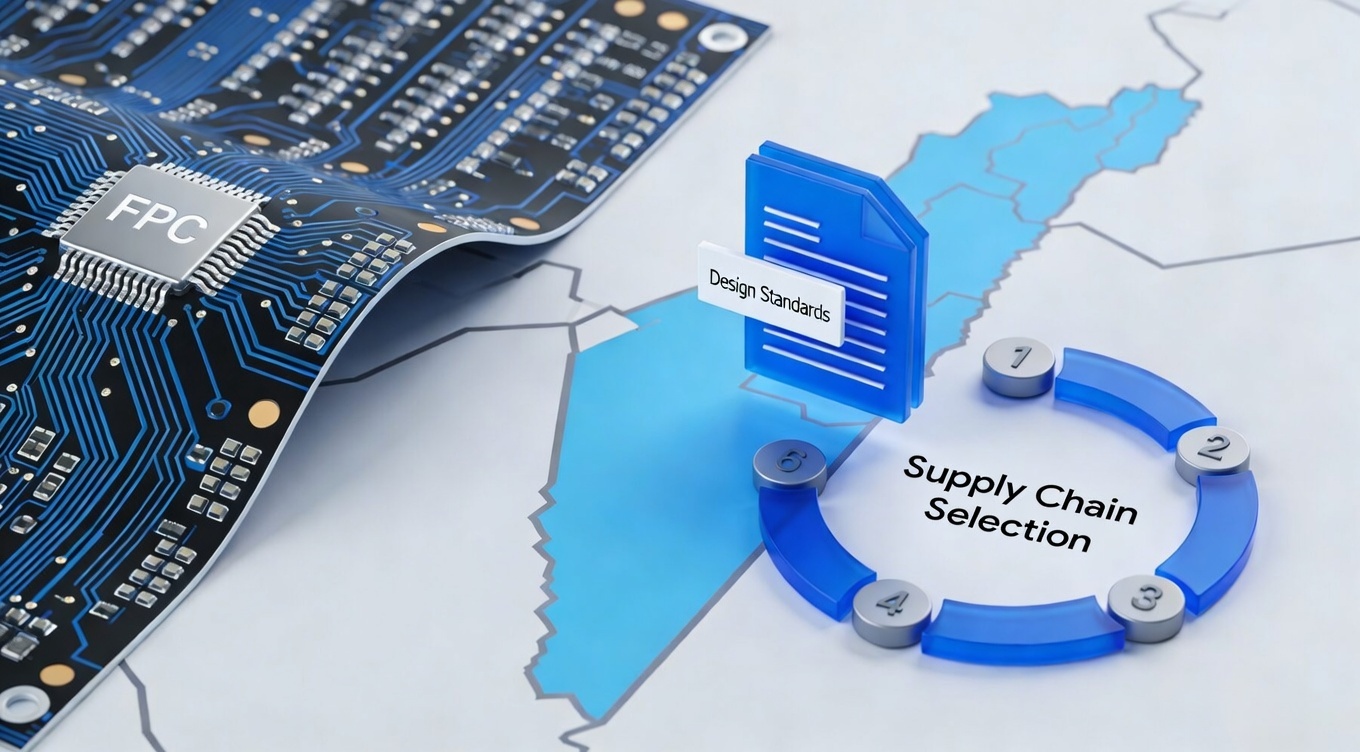
- H2: Best Practices for Designing Controlled Impedance FPCs
- H2: Long-Tail Keywords to Boost SEO Reach in Israel
- H2: Why Choose BESTFPC for Controlled Impedance FPC Solutions
- H2: Conclusion & Next Steps for Israel-Focused Buyers
Understanding FPC Impedance Control & Its Importance
Impedance control in FPCs (Flexible Printed Circuits) refers to the process of designing and manufacturing circuit traces so that they have a stable electrical impedance that matches design targets (e.g., 50 Ω single-ended, 90 Ω or 100 Ω differential impedance). This precision is vital for high-speed signal integrity, especially when transmission lines run at GHz speeds in modern electronics.
Flexible circuits are innately thin and lightweight, but their physical structure (e.g., dielectric thickness, copper dimensions) makes them more sensitive to manufacturing variation compared with rigid PCBs. This means that a small deviation in trace geometry or material properties can significantly affect the characteristic impedance, leading to signal reflections, data errors, and potential system failure.
In the context of Israel’s advanced tech and defense-oriented electronics markets, controlled impedance is not an optional enhancement — it’s a prerequisite for high-reliability communication modules, RF telemetry systems, and embedded processing units where signal integrity is essential. This section grounds readers in the core definition of FPC impedance control and explains why precise control is non-negotiable in high-performance applications.
Key Technical Factors that Determine Controlled Impedance in FPCs
Achieving a predictable and consistent impedance target involves careful control over multiple physical and material factors:
1. Trace Width & Spacing:
The width of copper traces and the spacing between differential pairs directly affect impedance values. Narrow traces increase impedance, whereas wider ones reduce it; both must be precisely specified and manufactured.
2. Dielectric Material & Thickness:
Materials such as polyimide (PI) are widely used due to their stable dielectric constant (~3.2–3.5). Variations in dielectric layer thickness have a direct impact on impedance, making material selection and thickness consistency critical.
3. Copper Weight & Uniformity:
Copper thickness influences conductor resistance and impedance. Manufacturing processes must ensure uniform copper plating and etching accuracy to maintain impedance tolerances.
4. Etching Tolerances:
PCB trace formation through etching must be tightly controlled; even small deviations can cause impedance mismatches. Advanced etching techniques and process controls mitigate this risk.
5. Referential Planes & Stack-Up:
Reference planes (ground/power layers) and overall stack-up configuration influence return paths and electromagnetic behavior. Proper map of layers ensures stable signal return and reduces impedance-related reflections.
6. Testing & Validation:
Techniques like Time Domain Reflectometry (TDR) are used to measure and verify actual impedance values post-manufacturing, ensuring real world compliance with design specifications.
This section deepens the technical discussion, showing Israel-based engineers how multiple design and manufacturing variables must be managed simultaneously to achieve consistent impedance control.
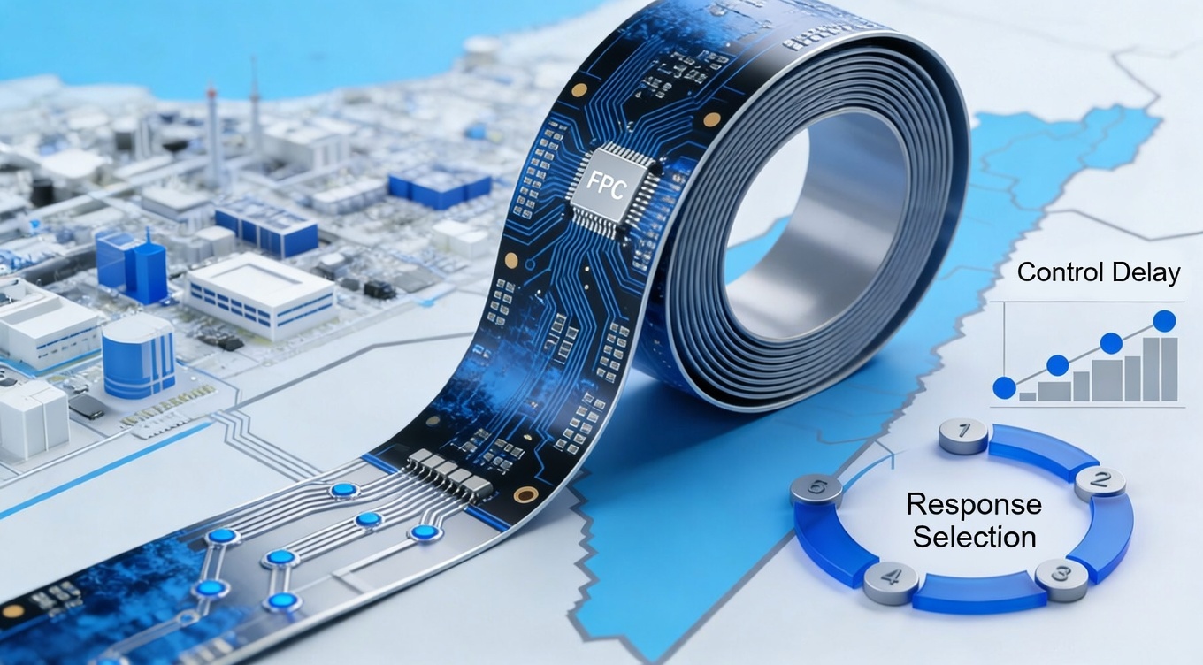
Israel’s Electronics & Signal-Sensitive Markets Driving Impedance Requirements
The Israeli electronics ecosystem features several sectors where controlled impedance in flexible PCB design directly impacts product success:
Telecommunications & Networking:
High-speed data transmission devices for 5G and broadband infrastructure require FPCs with minimal signal loss and precise impedance matching, especially for RF front ends and antenna interfaces.
Defense & Aerospace Electronics:
Compact, high-frequency systems used in guidance, telemetry, and secure communication modules rely on controlled impedance paths to maintain high signal fidelity under extreme environmental conditions.
Medical Devices & Wearables:
Medical imaging systems, diagnostic wearables, and sensor interfaces use flexible circuitry with tight impedance requirements to ensure accurate signal acquisition and data transfer.
IoT & Smart Devices:
As Israel’s IoT applications grow, controlled impedance becomes fundamental for reliable wireless communication and ultra-low power sensor networks.
Across these industries, improper impedance control can cause signal reflections, timing errors, and electromagnetic interference — all of which degrade performance or cause functional failures. Ultra-reliable systems common in Israeli high-tech sectors enforce stringent specifications for signal integrity that begin at the FPC design level. This deep dive ties impedance control to real market needs and purchasing considerations.
Industry Standards & Testing Methods for Impedance Control
While there isn’t a single mandatory global standard exclusively for impedance in FPCs, industry best practices and engineering benchmarks are widely referenced:
- Target Impedance Values: Common targets such as 50 Ω single-ended and 90 Ω–100 Ω differential are used for modern interfaces like USB, HDMI, and high-speed serial links.
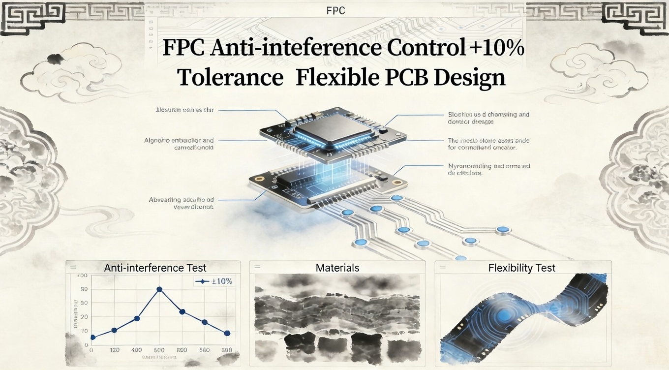
- Tolerance Benchmarks: ±10 % is a common manufacturing tolerance baseline, with tighter tolerances (±5 % or better) required for high-performance applications.
- Simulation Tools: Pre-production tools such as Polar SI9000 or HyperLynx predict impedance behavior and guide stack-up decisions.
- Measurement Techniques: Time Domain Reflectometry (TDR) is the standard method to validate impedance after fabrication, ensuring that manufactured boards match design intent.
For Israel-specific markets, recommending suppliers that can provide test reports and simulation documentation builds trust with purchasing engineers and procurement managers, especially for mission-critical applications.
Best Practices for Designing Controlled Impedance FPCs
Designing FPCs with reliable impedance control requires cross-functional collaboration between designers and manufacturers:
1.Specify Clear Impedance Targets Early:
Design documents should explicitly state desired impedance values and tolerances so fabrication teams can plan stack-up and trace geometry.
2.Use Controlled Materials:
Select substrates with stable dielectric constants and low variability, and match them with suitable coverlay choices.
3.Leverage Advanced Stack-Up & Grounding:
Incorporate continuous ground planes when possible and plan layer structures that reduce return path discontinuities.
4.Simulate Before Fabrication:
Run simulations to confirm trace geometry achieves impedance targets, reducing iteration cycles and time to market.
5.Prototyping With TDR Verification:
Prototype runs with impedance measurements provide empirical data that confirm manufacturing alignment with design goals.
This section provides Israeli engineering teams with actionable design and process tips that directly relate to their product performance outcomes.
Why Choose BESTFPC for Controlled Impedance FPC Solutions
At BESTFPC, our controlled impedance flexible PCB manufacturing integrates advanced engineering, simulation-assisted stack-up design, and rigorous process control to meet strict signal integrity requirements:
- Precision Impedance Engineering: Customized stack-up planning and trace modeling based on design specifications.
- TDR Testing & Verification: Impedance measurement validation available upon request to confirm production outcomes.
- High-Reliability Materials & Processes: Stable dielectric substrates and controlled etching ensure repeatable impedance performance.
- Internal High-Interaction Pages To Improve Engagement:
FPC Design Guidelines & Impedance Control
Flexible PCB Manufacturing Capabilities
High-Speed Signal Integrity Solutions
Conclusion & Next Steps for Israel-Focused Buyers
For Israel’s advanced technology sectors — from telecommunications to defense and medical devices — controlled impedance in FPCs is a foundational engineering requirement. Understanding its technical determinants, design best practices, and rigorous validation methods empowers purchasing teams and engineers to specify supplier expectations confidently.
If your project demands high-speed performance and predictable signal integrity, BESTFPC offers the precision engineering and manufacturing capabilities that align with demanding impedance control requirements — supporting quality, delivery, and technical transparency.
.png)
.png)
.png)
.png)

.png)

