


 2025-10-22
 BEST
BEST
When you select pi coverlay for your flex project, you must focus on flexibility, temperature resistance, adhesive type, and your specific application needs. Each flex circuit faces unique mechanical and environmental demands. You want the coverlay to withstand repeated flex cycles, support stable performance, and protect against harsh conditions. A strong adhesive ensures the flex layers stay intact during use. Proper thickness helps the flex circuit bend smoothly without cracking or losing function. Matching these properties to your flex requirements leads to reliable, long-lasting performance.
Key Takeaways
- Match the flexibility of the coverlay to your circuit's bending needs for optimal performance.
- Choose the right adhesive type based on your operating environment to ensure long-lasting reliability.
- Select the appropriate thickness of the coverlay to balance flexibility and protection for your design.
- Ensure the coverlay can withstand the maximum temperatures your application will face to prevent failures.
- Prioritize environmental protection features in the coverlay to enhance the lifespan of your flex circuit.
PI Coverlay Basics
What Is PI Coverlay
You use pi coverlay as a protective layer in flexible circuit designs. It consists of polyimide film and adhesive. This material covers and shields the copper traces on a pcb. You often see it in flexible printed circuit coverlay applications because it offers strong insulation and mechanical protection. Polyimide stands out among flexible circuit materials for its ability to handle high temperatures and repeated bending.
Role in Flex Circuits
Flexible printed circuit coverlay plays a critical role in the performance and durability of your pcb. You apply it to the outer layers of the circuit to protect against moisture, dust, and chemicals. It also prevents short circuits by insulating the conductive traces. When you select the right coverlay, you help your pcb survive harsh environments and frequent flexing. You also improve the reliability of connections and reduce the risk of electrical failure.
Tip: Always match the coverlay type to your pcb’s bending and environmental needs. This step ensures long-term performance.
Key Benefits
Flexible printed circuit coverlay brings several advantages to your pcb projects:
- Superior Flexibility: You can bend and twist the pcb without cracking the coverlay.
- Thermal Stability: The coverlay withstands soldering temperatures and high-heat environments.
- Chemical Resistance: It protects your pcb from solvents, oils, and other chemicals.
- Electrical Insulation: You reduce the risk of shorts and improve safety.
- Enhanced Durability: The coverlay extends the lifespan of your pcb by shielding it from physical and environmental damage.
You gain these benefits when you choose the right coverlay for your application. This choice helps you build reliable, high-performance flexible circuits.
Selection Criteria for PI Coverlay
When you select pi coverlay for your flex pcb design, you must match its properties to your application’s unique requirements. Each flex circuit faces different mechanical and environmental stresses. You need to consider how the coverlay will perform under repeated bending, high temperature, and exposure to chemicals or moisture. The right choice of flex pcb materials ensures your design meets reliability and durability standards.
Flexibility
Flexibility stands as a core requirement in flex pcb design. You want your pi coverlay to bend and twist with the circuit without cracking or delaminating. If your design includes tight bends or dynamic movement, choose a coverlay with high elongation and low modulus. This allows the flex circuit to move freely and maintain electrical integrity. For static applications, you can select a stiffer coverlay, but most flex designs benefit from maximum flexibility. Always test the coverlay’s performance in your specific flex environment to avoid premature failure.
Adhesive Types
The adhesive in your pi coverlay directly affects the bond strength and long-term reliability of your flex pcb design. You will typically choose between epoxy and acrylic adhesives. Each type offers distinct advantages and trade-offs:
| Adhesive Type | Properties | Impact on Circuit Performance |
|---|---|---|
| Epoxy | Lower temperature, strong bonding, sensitive to storage | Affects durability and reliability under varying conditions |
| Acrylic | Longer shelf life, higher processing cost | Influences long-term performance and cost-effectiveness |
Epoxy adhesives provide strong bonds but may degrade if exposed to high temperature or improper storage. Acrylic adhesives offer better shelf life and can handle a wider range of processing conditions, but they may increase your overall design cost. Select the adhesive that aligns with your flex pcb design’s operating environment and expected lifespan.
Thickness
Thickness plays a critical role in both flexibility and protection. Standard pi coverlay thickness ranges from 25 to 50μm. Thinner coverlays allow for tighter bends and greater flexibility, which is ideal for dynamic flex applications. Thicker coverlays provide enhanced mechanical protection and insulation, which you may need in rugged environments. When you design your flex pcb, balance the need for flexibility with the level of protection required. Too thick a coverlay can hinder bending, while too thin may not provide enough shielding.
Temperature Resistance
Temperature resistance is essential in high-reliability flex pcb design. You must ensure your pi coverlay can withstand the thermal demands of both assembly and operation. Polyimide coverlay can handle continuous operating temperatures up to 400°C. This makes it suitable for applications like automotive electronics, aerospace, and industrial controls, where circuits face extreme heat. If your design involves soldering or exposure to high temperature, always verify the coverlay’s rating to prevent thermal damage or adhesive failure.
- Polyimide (PI) coverlay can withstand continuous operating temperatures up to 400°C.
Environmental Protection
Environmental hazards such as moisture, chemicals, and dust can compromise your flex pcb design. Pi coverlay acts as a barrier, shielding your circuit from these threats. The coverlay, often made from polyimide or polyester films, laminates over the conductor layer to provide insulation and protection. This layer is crucial for maintaining circuit durability in high-density designs, including smartphones and automotive systems. You gain insulation and protection similar to a solder mask on rigid PCBs, but with the added flexibility needed for flex circuits.
Note: Always evaluate the environmental conditions your flex pcb design will face. Select a pi coverlay that offers the right balance of flexibility, temperature resistance, and chemical protection for your application.
Key Takeaways for PI Coverlay Selection:
- Match coverlay flexibility to your design’s bending requirements.
- Choose the adhesive type based on your operating environment and reliability needs.
- Select the appropriate thickness for your flex pcb design’s mechanical and insulation demands.
- Ensure the coverlay can withstand the maximum temperature your application will encounter.
- Prioritize environmental protection to extend the lifespan of your flex circuit.
By carefully considering these criteria, you can optimize your flex pcb design for performance, reliability, and longevity.
Double-Sided Flexible PCB Coverlay
Manufacturing Process
When you work with double-sided flexible pcb coverlay, you face a more complex fpc coverlay process than with single-sided designs. You must prepare both sides of the flex circuit for protection and insulation. The process starts with careful material preparation. You store the films at 5°C and let them reach room temperature to avoid moisture condensation. Next, you create window openings for pad access using CNC drilling or punching. This step ensures precise alignment for both sides.
You then clean the surface to remove oxidation and contaminants. Proper cleaning helps the adhesive bond well during the fpc coverlay process. After cleaning, you manually align the coverlay film with the circuit pattern. You secure it temporarily with a soldering iron. This step is critical for double-sided flexible pcb coverlay because misalignment can cause defects on both sides.
Lamination follows. You use heat and pressure, typically at 160–200°C for 1.5–2 hours, in a vacuum press. This ensures strong adhesion and bubble-free coverage. Silkscreen printing may be used for marking or adding legends, but it offers lower durability and is best for simple flex applications. Quality control checks every stage of the fpc coverlay process to catch defects early.
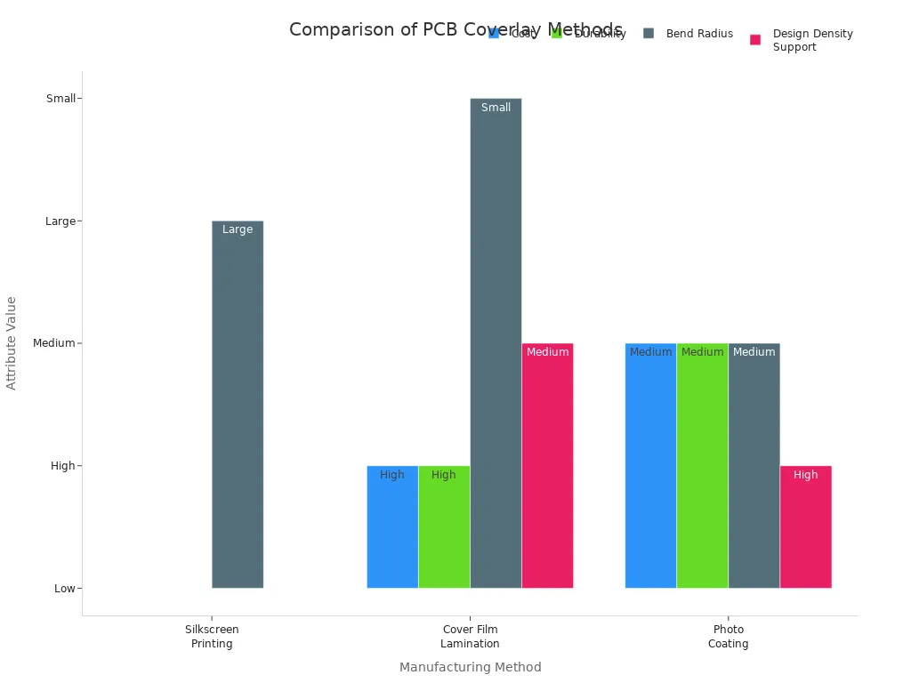
| Method | Cost | Durability | Bend Radius | Design Density Support | Applications |
|---|---|---|---|---|---|
| Silkscreen Printing | Low | Low | Large | Low | Remote controls, dashboard wiring |
| Cover Film Lamination | High | High | Small | Medium | Wearable monitors, foldable smartphones |
| Photo Coating | Medium | Medium | Medium | High | 5G antennas, medical sensors |
Tip: Always monitor temperature and pressure during lamination. This step prevents delamination and ensures long-term flex reliability.
Application Considerations
You should choose double-sided flexible pcb coverlay when your flex design needs protection and insulation on both sides. This is common in high-density circuits, wearable devices, and foldable electronics. Double-sided coverlay supports tighter bend radii and higher reliability. If your flex circuit faces frequent movement or harsh environments, this approach gives you better durability.
The fpc coverlay process for double-sided flexible pcb coverlay also allows for more complex routing and higher circuit density. You gain the ability to add more components and traces without sacrificing flexibility. However, you must balance cost, bend radius, and durability. For simple or low-cost flex designs, single-sided coverlay or silkscreen printing may be enough. For advanced applications, double-sided flexible pcb coverlay offers the best performance.
PI Coverlay vs. Alternatives
Liquid Photoimageable Solder Mask
When you design a flex pcb, you may consider liquid photoimageable solder mask as an alternative to traditional PI coverlay. This material uses a light-sensitive process to define fine features on your flex pcb. You apply the solder mask as a liquid, then expose it to UV light through a patterned film. This method allows you to achieve high precision and sharp edges on your flex pcb. Many engineers choose this option for flex pcb designs that require tight tolerances and complex layouts.
However, liquid photoimageable solder mask does not offer the same mechanical durability as PI coverlay. You may notice that it performs well in static flex pcb applications, but it can crack or delaminate under repeated bending. If your flex pcb will experience frequent movement, you should carefully evaluate whether this alternative meets your reliability needs.
| Characteristic | PI Coverlay | Liquid Photoimageable Solder Mask |
|---|---|---|
| Flexibility | Enhanced flexibility for dynamic applications | May have lower mechanical durability |
| Temperature Resistance | Superior mechanical strength | High precision but less durable |
| Process Compatibility | Suitable for high-density designs | Uses light-sensitive materials for fine feature definition |
Tip: For dynamic flex pcb applications, PI coverlay remains the preferred choice due to its superior flexibility and temperature resistance.
Pros and Cons
You face several options when selecting a coverlay method for your flex pcb. Each method brings unique advantages and limitations. PI coverlay stands out for its high durability and suitability for demanding flex pcb environments. Silkscreen printing offers a cost-effective solution for simple flex pcb designs, but it lacks the mechanical strength needed for advanced applications. Photo coating provides a balance between cost and performance, making it suitable for specialized flex pcb uses like medical sensors.
| Coverlay Method | Cost | Durability | Applications |
|---|---|---|---|
| PI Coverlay | High | High | Wearable monitors, foldable smartphones |
| Silkscreen Printing | Low | Low | Remote controls, dashboard wiring |
| Photo Coating | Medium | Medium | 5G antennas, medical sensors |
When you choose a coverlay for your flex pcb, consider the specific demands of your application. PI coverlay delivers the best results for high-reliability flex pcb projects. If your flex pcb requires frequent bending or exposure to harsh environments, this method ensures long-term performance. For less demanding flex pcb designs, alternatives may offer cost savings, but you may sacrifice durability.
Remember: Always match your coverlay choice to the flex pcb’s mechanical and environmental requirements to achieve optimal results.
High-Temperature Flex PCBs
Material Selection
When you design high-temperature flex pcbs, you must focus on selecting materials that can handle extreme temperature conditions. Polyimide stands out as the preferred choice for flex circuits in high-temperature applications. This material offers excellent thermal stability and resists degradation even when exposed to temperatures up to 200°C. You should also consider all-polyimide constructions, which maximize service temperature performance and minimize the risk of material breakdown. High-temperature adhesives play a crucial role in maintaining the bond between layers, ensuring your flex pcb remains reliable under thermal stress. Heat-resistant materials with high creep resistance help prevent permanent deformation and stress relaxation during prolonged exposure to elevated temperature.
| Material Property | Importance |
|---|---|
| Thermal Stability | Polyimide can endure temperatures up to 200°C, ideal for high-temperature applications. |
| All-Polyimide Constructions | Maximizes service temperature performance and minimizes degradation. |
| High-Temperature Adhesives | Maintains bonding strength and integrity under elevated thermal conditions. |
| Heat-Resistant Materials | High creep resistance combats permanent deformation at high temperatures. |
Tip: Always verify the temperature rating of your flex materials before finalizing your pcb design.
Performance Factors
You will notice that polyimide coverlay outperforms other materials in high-temperature flex pcbs. Polyimide withstands high temperatures up to 200°C, making it the best option for high-temperature applications. Other coverlay materials often lose dielectric properties at elevated temperature, but polyimide maintains stability. You benefit from low moisture absorption (0.5%), which helps your flex pcb perform reliably even in challenging environments.
- Polyimide can withstand high temperatures up to 200°C, making it superior in high-temperature stability compared to other materials.
- Elevated temperatures can lead to degradation of dielectric properties in flex board materials, which is a challenge not faced by polyimide to the same extent.
- Polyimide has low moisture absorption (0.5%), which helps maintain its performance under high-temperature conditions.
When you select the right materials and understand these performance factors, your high-temperature flex pcbs will deliver consistent results in demanding applications. This approach ensures your pcb can handle the rigors of high-temperature environments, such as automotive, aerospace, and industrial controls.
Step-by-Step Selection Guide
Selecting the right PI coverlay for your flex pcb project requires a structured approach. You can follow these steps to ensure your flex circuit meets all performance and reliability standards.
Define Application Needs
Start by identifying the specific requirements of your flex pcb. You need to consider the environment where your flex circuit will operate. Will your flex pcb face high temperatures, frequent bending, or exposure to chemicals? List all mechanical stresses and environmental hazards. You should also determine the minimum bend radius and the number of flex cycles your pcb must withstand.
Ask yourself these questions:
- What is the primary function of your flex pcb?
- Will the flex circuit move repeatedly, or will it remain static?
- Does your application require resistance to moisture, dust, or chemicals?
- What are the maximum and minimum temperatures your flex pcb will encounter?
You can use a simple checklist to organize your needs:
| Requirement | Details/Notes |
|---|---|
| Flex cycles | |
| Minimum bend radius | |
| Operating temperature | |
| Chemical exposure | |
| Required thickness | |
| Electrical insulation |
Tip: The more clearly you define your flex pcb’s needs, the easier it becomes to select the right coverlay.
Evaluate Material Specs
Once you know your application needs, you should compare the specifications of available PI coverlay materials. Review the datasheets for each option. Focus on properties such as flexibility, adhesive type, thickness, and temperature resistance.
You want to match the flex requirements of your pcb to the coverlay’s capabilities. For example, if your flex pcb will bend frequently, select a coverlay with high elongation and low modulus. If your flex pcb will operate in a harsh environment, prioritize chemical and moisture resistance.
Consider these key material specs:
- Flexibility: Choose a coverlay that matches your flex pcb’s bend radius and movement cycles.
- Adhesive Type: Select between epoxy and acrylic based on your flex pcb’s temperature and reliability needs.
- Thickness: Balance protection and flexibility for your flex pcb.
- Temperature Resistance: Ensure the coverlay can handle your flex pcb’s operating and assembly temperatures.
- Environmental Protection: Confirm the coverlay shields your flex pcb from moisture, chemicals, and dust.
You can create a comparison table to help visualize your options:
| Coverlay Option | Flexibility | Adhesive Type | Thickness | Temp Resistance | Environmental Protection |
|---|---|---|---|---|---|
| Option A | High | Epoxy | 25μm | 200°C | Good |
| Option B | Medium | Acrylic | 50μm | 180°C | Excellent |
| Option C | High | Acrylic | 38μm | 220°C | Good |
Note: Always request samples or technical data from your supplier to verify the specs for your flex pcb.
Prototype and Test
After you select the most suitable PI coverlay, you should build a prototype of your flex pcb. Testing in real-world conditions helps you confirm that your flex circuit performs as expected. You want to check for issues such as delamination, cracking, or adhesive failure.
Follow these steps during prototyping:
- Fabricate a small batch of your flex pcb using the chosen coverlay.
- Perform mechanical tests, such as repeated bending and flexing.
- Expose your flex pcb to the expected temperature and environmental conditions.
- Inspect for any signs of wear, delamination, or electrical failure.
- Gather feedback from your engineering team or end users.
If you find any problems, adjust your material selection or process. Repeat the testing until your flex pcb meets all requirements.
.png)
.png)
.png)
.png)

.png)

